Texas Instruments TL1464I Data Sheet
Summary
The TL1464I is a high-precision quad PWM controller IC built for regulating stable, high-efficiency linear and switching power supplies. It integrates critical features into a single chip, including multiple error amplifiers, undervoltage lockout circuitry, and transient protection. This manual provides power electronics engineers with comprehensive data on the circuit's functional block diagram, signal flow, operational parameters, and detailed pin assignments necessary for designing reliable quad-channel DC power applications.
Page 1 Text Content
查询TL1464供应商 TL1464I
QUAD PULSE-WIDTH-MODULATION CONTROL CIRCUIT
SLVS266 – FEBRUARY 2000
High-Speed Drive Controller for PNP Power Internal Short-Circuit Protection Transistor
Internal Undervoltage Lockout Protection
Internal-Regulator Provides a Stable 1.5 V
Internal Shut-Down Circuit by Channel
Reference Supply
Controllable Base Current of External
Low Start-Up Voltage 3.1 V
Transistor
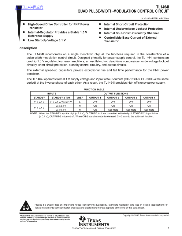
description The TL1464I incorporates on a single monolithic chip all the functions required in the construction of a pulse-width-modulation control circuit. Designed primarily for power supply control, the TL1464I contains an on-chip 1.5 V regulator, four error amplifiers, an oscillator, two dead-time comparators, undervoltage lockout circuitry, short circuit protection, standby control circuitry, and output circuits. The external speed-up capacitors provide exceptional rise and fall time performance for the PNP power transistor. The TL1464I operates from 3.1 V supply voltage and 2 pair of four-outputs (CH-1/CH-3, CH-2/CH-4 the same period) at the inverse phase of each other. As a result, the TL1464I provides high-efficiency power supply.
FUNCTION TABLE
INPUTS OUTPUT FUNCTIONS
STANDBY STANDBY-2 TO4 VREF OUTPUT-1 OUTPUT-2 OUTPUT-3 OUTPUT-4 VI ≤ 0.4 V VI ≤ 0.4 V, VI ≥ 2.4 V OFF OFF OFF OFF
VI ≥ 2.4 V ON ON ON ON
VI ≥ 0.4 V ON See Note See Note See Note
NOTE: When the STANDBY input is high (≥ 2.4 V), OUTPUT-2 to 4 are controlled individually. If STANDBY-2 input is low (≤ 0.4 V), OUTPUT-2 is turned off. When CH-2 standby mode is released, CH-2 can do the soft-start function.
Please be aware that an important notice concerning availability, standard warranty, and use in critical applications of Texas Instruments semiconductor products and disclaimers thereto appears at the end of this data sheet.
Copyright 2000, Texas Instruments Incorporated PRODUCTION DATA information is current as of publication date.
Products conform to specifications per the terms of Texas Instruments standard warranty. Production processing does not necessarily include testing of all parameters.
1POST OFFICE BOX 655303 • DALLAS, TEXAS 75265
Page Summary Contents For Texas Instruments TL1464I Data Sheet
Manual Details
| Brand | Texas Instruments |
|---|---|
| Pages | 11 |
| File Size | 167.12 KB |
| Published | May 29, 2026 |
Enter the captcha to get the download link:

Frequently Asked Questions
What system functions are integrated into the TL1464I chip?
It incorporates an on-chip 1.5 V regulator, four error amplifiers, an oscillator, dead-time comparators, UVLO circuitry, and short circuit protection.
What is the required supply voltage for this module to operate?
The TL1464I operates from a minimum 3.1 V supply voltage.
How do external capacitors affect performance?
External speed-up capacitors provide exceptional rise and fall time performance for the PNP power transistor.
What protection features are included in the design?
The circuit includes undervoltage lockout circuitry, short circuit protection, and standby control logic.