# A B C D E F G H I J K L M N O P Q R S T U V W X Y Z

Texas Instruments TPIC1021A-Q1 Data Handbook/Manual

Summary

This TI TPIC1021A-Q1 is a robust LIN physical layer interface designed for automotive applications. It integrates a transceiver, wake-up circuitry, and protection features to support LIN bus speeds up to 20 kbps. The device ensures reliable communication in harsh environments with high ESD immunity and fault protection, making it ideal for master and slave nodes using 5V or 3.3V I/O.
📄 Preview 📖 Table of Contents Contents PAGE OF 18

Page 1 Text Content

TPIC1021A-Q1

LIN PHYSICAL INTERFACE

www.ti.com

SLIS117–AUGUST

FEATURES

LIN Physical Layer Specification Revision 2.0 Dominant State Timeout Protection

Compliant and Conforms to SAEJ2602

Wake-Up Request on RXD Pin

Recommended Practice for LIN

Control of External Voltage Regulator

LIN Bus Speed up to 20-kbps LIN Specified

(INH Pin)

Maximum

Integrated Pullup Resistor and Series Diode

Sleep Mode: Ultralow Current Consumption,

for LIN Slave Applications

Allows Wake-Up Events From LIN Bus,

Low Electromagnetic Emission (EME), High

Wake-Up Input (External Switch), or Host MCU

Electromagnetic Immunity (EMI)

High-Speed Receive Capable

Bus Terminal Short Circuit Protected for

ESD Protection to ±12 k V (Human-Body

Short to Battery or Short to Ground

Model) on LIN Pin

Thermally Protected

LIN Pin Handles Voltage From –40 to

Ground Disconnection Fail Safe at System

Survives Transient Damage in Automotive

Level

Environment (ISO 7637)

Ground Shift Operation at System Level

Extended Operation With Supply From to

Unpowered Node Does Not Disturb the

DC (LIN Specification to V)

Network

Interfaces to MCU With 5-V or 3.3-V I/O Pins

Supports ISO9141 (K-Line)-Like Functions

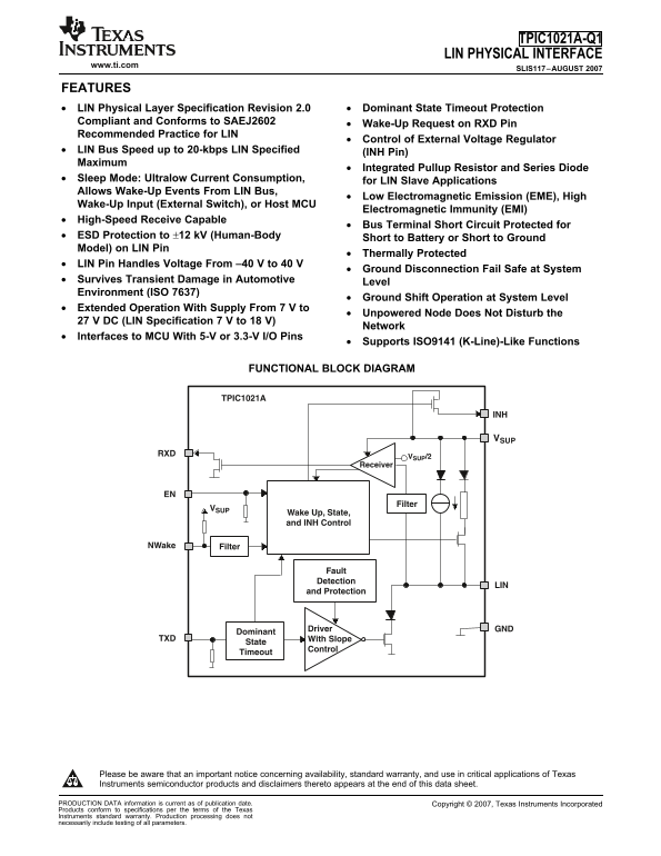
FUNCTIONAL BLOCK DIAGRAM

TPIC1021A

VSUP/2

Receiver

Filter

Wake Up, State, and INH Control

NWake Filter

Fault Detection

and Protection

Driver GND

Dominant

TXD With Slope

State

Control

Timeout

Please be aware that an important notice concerning availability, standard warranty, and use in critical applications of Texas

Instruments semiconductor products and disclaimers thereto appears at the end of this data sheet.

PRODUCTION DATA information is current as of publication date. Copyright 2007, Texas Instruments Incorporated

Products conform to specifications per the terms of the Texas

Instruments standard warranty. Production processing does not

necessarily include testing of all parameters.

Page Summary Contents For Texas Instruments TPIC1021A-Q1 Data Handbook/Manual

Page 1 TPIC1021A-Q1 LIN PHYSICAL INTERFACE www.ti.com SLIS117–AUGUST FEATURES LIN Physical Layer Specification Revision 2.0 Dominant State Timeout Protection Compliant and Conforms to SAEJ2602 Wake-Up Reques...
Page 2 TPIC1021A-Q1 LIN PHYSICAL INTERFACE www.ti.com SLIS117–AUGUST DESCRIPTION The TPIC1021A is the Local Interconnect Network (LIN) physical interface, which integrates the serial transceiver with wake-up...
Page 3 TPIC1021A-Q1 LIN PHYSICAL INTERFACE www.ti.com SLIS117–AUGUST Local Interconnect Network (LIN) Bus This I/O pin is the single-wire LIN bus transmitter and receiver. Transmitter Characteristics The dri...
Page 4 TPIC1021A-Q1 LIN PHYSICAL INTERFACE www.ti.com SLIS117–AUGUST Ground (GND) GND is the TPIC1021A device ground connection. The TPIC1021A can operate with ground shift as long as the ground shift does n...
Page 5 TPIC1021A-Q1 LIN PHYSICAL INTERFACE www.ti.com SLIS117–AUGUST OPERATING STATES Unpowered System Vsup sup_under£ Vsup sup_under£ sup sup_under Vsup sup_under£V Vsup sup_under£ sup sup_under V EN = high...
Page 6 TPIC1021A-Q1 LIN PHYSICAL INTERFACE www.ti.com SLIS117–AUGUST While the device is in sleep mode, the following conditions exist: The LIN bus driver is disabled and the internal LIN bus termination is ...
Page 7 TPIC1021A-Q1 LIN PHYSICAL INTERFACE www.ti.com SLIS117–AUGUST LIN 0.6 V× 0.6 V× SUP SUP 0.4 × VSUP 0.4 V× SUP t < t LINBUS t LINBUS INH High Impedance t > tgo_to_operate RXD Floating MODE Sleep ...
Page 8 TPIC1021A-Q1 LIN PHYSICAL INTERFACE www.ti.com SLIS117–AUGUST ABSOLUTE MAXIMUM RATINGS over operating free-air temperature range (unless otherwise noted) PARAMETER RATING UNIT Continuous to VSUP Suppl...
Page 9 TPIC1021A-Q1 LIN PHYSICAL INTERFACE www.ti.com SLIS117–AUGUST ELECTRICAL CHARACTERISTICS VSUP to V, TA –40°C to 125°C (unless otherwise noted) PARAMETER TEST CONDITIONS MIN TYP MAX UNIT SUPPLY Device ...
Page 10 TPIC1021A-Q1 LIN PHYSICAL INTERFACE www.ti.com SLIS117–AUGUST ELECTRICAL CHARACTERISTICS (continued) VSUP to V, TA –40°C to 125°C (unless otherwise noted) PARAMETER TEST CONDITIONS MIN TYP MAX UNIT LI...
Page 11 TPIC1021A-Q1 LIN PHYSICAL INTERFACE www.ti.com SLIS117–AUGUST ELECTRICAL CHARACTERISTICS (continued) VSUP to V, TA –40°C to 125°C (unless otherwise noted) PARAMETER TEST CONDITIONS MIN TYP MAX UNIT AC...
Page 12 TPIC1021A-Q1 LIN PHYSICAL INTERFACE www.ti.com SLIS117–AUGUST TIMING DIAGRAMS t Bit t Bit RECESSIVE TXD (Input) DOMINANT THRec(max) Thresholds: LIN Bus Worst case 1 THDom(max) Signal THRec(min) Thresh...
Page 13 TPIC1021A-Q1 LIN PHYSICAL INTERFACE www.ti.com SLIS117–AUGUST TIMING DIAGRAMS (continued) LIN Bus 0.6 VSUP 0.4 VSUP trx_pdf trx_pdr Figure 6. Propagation Delay TPIC1021A RXD INH NWake Figure 7. Test C...
Page 14 TPIC1021A-Q1 LIN PHYSICAL INTERFACE www.ti.com SLIS117–AUGUST APPLICATION INFORMATION TPIC7xxxx MASTER VSUP NODE NWake VDD VSUPINH Master Node Pullup(3) VDD EN I/O MCU w/o (2) 1 k pullup VDD I/O TPIC1...
Page 15 TPIC1021A-Q1 LIN PHYSICAL INTERFACE www.ti.com SLIS117–AUGUST APPLICATION INFORMATION (continued) Device Comparison: TPIC1021 vs TPIC1021A The TPIC1021A is pin-to-pin compatible to the TPIC1021 device...
Page 16 PACKAGE OPTION ADDENDUM www.ti.com 22-Oct-2007 PACKAGING INFORMATION Orderable Device Status Package Package Pins Package Eco Plan Lead/Ball Finish MSL Peak Temp Type Drawing Qty TPIC1021AQDRQ1 ACTIVE...
Page 18 IMPORTANT NOTICE Texas Instruments Incorporated and its subsidiaries (TI) reserve the to make corrections, modifications, enhancements, improvements, and other changes to its products and services at ...

Manual Details

Brand Texas Instruments
Pages 18
File Size 278.21 KB
Published June 15, 2026
6 views

Enter the captcha to get the download link:

captcha

Frequently Asked Questions

What is the maximum LIN bus speed supported?

The LIN bus speed is up to 20 kbps, as specified.

How does wake-up from sleep mode work?

Wake-up can be triggered remotely via the LIN bus or locally via the NWake or EN pins.

Do slave applications require an external pullup resistor?

No, slave applications use the internal 30 kΩ pullup resistor and series diode; no external components are needed.

What is the supply voltage operating range?

It operates with a supply from 7 V to 27 V DC, extending beyond the LIN specification of 7 V to 18 V.

What fault protections are integrated?

The device has undervoltage, overtemperature, loss-of-ground, short-circuit, and ESD protection to ±12 kV.