# A B C D E F G H I J K L M N O P Q R S T U V W X Y Z

Texas Instruments ADS1202 Data Handbook/Manual

Summary

The ADS1202 is a high-precision 16-bit Sigma-Delta Analog-to-Digital Converter designed for robust industrial measurement in challenging environments. This technical guide provides comprehensive details on its operation, featuring reliable performance from a single +5V supply and ideal differential input handling. Professionals in industrial process control, motor management, smart transmitter development, and weight scale applications will find detailed specifications covering resolution, linearity, power ratings, and diverse operational modes for seamless integration into demanding systems.
📄 Preview PAGE OF 21

Page 1 Text Content

查询ADS1202供应商

ADS1202

SBAS275 – DECEMBER 2002

Motor Control Current Shunt

1-Bit, 10MHz, 2nd-Order, Delta-Sigma Modulator FEATURES DESCRIPTION

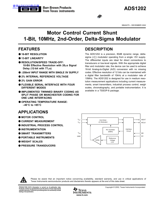
16-BIT RESOLUTION The ADS1202 is a precision, 80d B dynamic range, delta- sigma (∆∑) modulator operating from a single +5V supply.

13-BIT LINEARITY

The differential inputs are ideal for direct connections to

RESOLUTION/SPEED TRADE-OFF:

transducers or low-level signals. With the appropriate digital

10-Bit Effective Resolution with 20µs Signal

filter and modulator rate, the device can be used to achieve

Delay (12-bit with 77µs)

16-bit Analog-to-Digital (A/D) conversion with no missing ±250m V INPUT RANGE WITH SINGLE 5V SUPPLY codes. Effective resolution of 12 bits can be maintained with a digital filter bandwidth of 10k Hz at a modulator rate of

2% INTERNAL REFERENCE VOLTAGE

10MHz. The ADS1202 is designed for use in medium reso-

2% GAIN ERROR

lution measurement applications including current measure- FLEXIBLE SERIAL INTERFACE WITH FOUR ments, smart transmitters, industrial process control, weigh DIFFERENT MODES scales, chromatography, and portable instrumentation. It is available in a TSSOP-8 package.

IMPLEMENTED TWINNED BINARY CODING AS SPLIT PHASE OR MANCHESTER CODING FOR ONE LINE INTERFACING OPERATING TEMPERATURE RANGE: –40°C to +85°C

APPLICATIONS MOTOR CONTROL

VIN+ MDAT

2nd-Order

CURRENT MEASUREMENT ∆∑ Modulator

VIN– MCLK

INDUSTRIAL PROCESS CONTROL

INSTRUMENTATION Interface

RC Oscillator

Circuit

20MHz

VDD M0

SMART TRANSMITTERS

GND M1

PORTABLE INSTRUMENTS Reference

Buffer Voltage

WEIGHT SCALES 2.5V

PRESSURE TRANSDUCERS

Please be aware that an important notice concerning availability, standard warranty, and use in critical applications of Texas Instruments semiconductor products and disclaimers thereto appears at the end of this data sheet.

PRODUCTION DATA information is current as of publication date. Copyright © 2002, Texas Instruments Incorporated Products conform to specifications per the terms of Texas Instruments standard warranty. Production processing does not necessarily include testing of all parameters.

www.ti.com

Page Summary Contents For Texas Instruments ADS1202 Data Handbook/Manual

Page 1 查询ADS1202供应商 ADS1202 SBAS275 – DECEMBER 2002 Motor Control Current Shunt 1-Bit, 10MHz, 2nd-Order, Delta-Sigma Modulator FEATURES DESCRIPTION 16-BIT RESOLUTION The ADS1202 is a precision, 80d B dynamic...
Page 2 ABSOLUTE MAXIMUM RATINGS ELECTROSTATIC Over operating free-air temperature (unless otherwise noted)(1) DISCHARGE SENSITIVITY Supply Voltage, GND to VDD –0.3V to 6V Analog Input Voltage Range GND – 0.4...
Page 3 ELECTRICAL CHARACTERISTICS Over recommended operating free-air temperature range at –40°C to +85°C, VDD = 5V, +In = –250m V to 250m V, –In = 0V, and MCLK = 10MHz, unless otherwise noted. ADS1202IPW PA...
Page 4 TIMING DIAGRAMS DIAGRAM 1: Mode 0 Operation. DIAGRAM 2: Mode 1 Operation. DIAGRAM 3: Mode 2 Operation. ADS12024 SBAS275www.ti.com
Page 5 TIMING DIAGRAMS (Cont.) DIAGRAM 4: Mode 3 Operation. TIMING CHARACTERISTICS over recommended operating free-air temperature range –40°C to +85°C, VDD = 5V, and MCLK = 10MHz, unless otherwise noted. SP...
Page 6 TYPICAL CHARACTERISTICS ffs et µV VDD = 5V, +In = –250m V to 250m V, –In = 0V, and MCLK = 10MHz, unless otherwise noted. IN (L IN (L INTEGRAL NONLINEARITY vs INPUT SIGNAL (Mode 0) INTEGRAL NONLINEARIT...
Page 7 TYPICAL CHARACTERISTICS (Cont.) VDD = 5V, +In = –250m V to 250m V, –In = 0V, and MCLK = 10MHz, unless otherwise noted. IN d B d B oi se µV RMS NOISE vs INPUT VOLTAGE LEVEL SIGNAL-TO-NOISE RATIO vs TEM...
Page 8 TYPICAL CHARACTERISTICS (Cont.) ag ni tu de d B VDD = 5V, +In = –250m V to 250m V, –In = 0V, and MCLK = 10MHz, unless otherwise noted. LK z) d B SPURIOUS-FREE DYNAMIC RANGE SPURIOUS-FREE DYNAMIC RANGE...
Page 9 TYPICAL CHARACTERISTICS (Cont.) VDD = 5V, +In = –250m V to 250m V, –In = 0V, and MCLK = 10MHz, unless otherwise noted. POWER-SUPPLY REJECTION RATIO d B ur re nt vs FREQUENCY HISTOGRAM OF OUTPUT DATA u...
Page 10 GENERAL DESCRIPTION THEORY OF OPERATION The differential analog input of the ADS1202 is implemented The ADS1202 is a single-channel, 2nd-order, CMOS analog with a switched capacitor circuit. This swit...
Page 11 ANALOG INPUT STAGE the linearity of the device is ensured only when the analog voltage applied to either input resides within the range defined Analog Input by –320m V and +320m V. The input design to...
Page 12 DIGITAL OUTPUT ods can be used to obtain this synchronization. The first method has the delta-sigma modulator and the filter receive The timing diagram for the ADS1202 data retrieval is shown the cloc...
Page 13 Interface Circuit Decoder INTCLK MUX1 RC Oscillator EXTCLK Code Generator MUX2 CLK/2 MDAT MCLK OCLK CLK/4 CLK DATA Modulator FIGURE 5. Flexible Interface Block Diagram. The code generator receives the...
Page 14 Mode 0 Mode 1 In mode 0 both input signals, M0 and M1, are LOW. The In mode 1, the input signal M0 is HIGH and M1 is LOW (see control signal coming from the decoder enables the internal Table I). The ...
Page 15 Mode 2 Mode 3 In mode 2, M0 is low and M1 is HIGH (see Table I). The control mode 3 is similar to mode 0; the only difference is that an signal coming from the decoder enables the internal RC oscil- e...
Page 16 APPLICATIONS The DSP can be directly connected at the output of two channels of the optocoupler, C28x or C24x. In this configu- Mode 0 operation in a typical application is shown in Figure ration, the...
Page 17 Floating HV+ Power Supply Gated Drive Circuit ADS1202 R4 Optocoupler M0 VDD VIN+ MCLK or VIN– MDAT C24x RSENSE 0.1µF M1 GND Power Supply Gated Drive Circuit FIGURE 11. Application Diagram in Mode 2. F...
Page 18 ADS1202 C4 M0 VDD VIN+ MCLK VIN– MDAT RSENSE C1 0.1µF M1 GND ADS1202 C5 M0 VDD VIN+ MCLK VIN– MDAT RSENSE C2 0.1µF M1 GND C28x or C24x ADS1202 C6 M0 VDD 27Ω SPICLK VIN+ MCLK SPISIMO VIN– MDAT RSENSE C...
Page 19 PACKAGE DRAWING PW (R-PDSO-G**) PLASTIC SMALL-OUTLINE PACKAGE 14 PINS SHOWN 0,15 NOM Gage Plane Seating Plane 1,20 MAX 0,10 PINS ** DIM A MAX 3,10 5,10 5,10 6,60 7,90 9,80 A MIN 2,90 4,90 4,90 6,40 7,...
Page 20 MECHANICAL DATA MTSS001C – JANUARY 1995 – REVISED FEBRUARY 1999 PW (R-PDSO-G**) PLASTIC SMALL-OUTLINE PACKAGE 14 PINS SHOWN 0,15 NOM Gage Plane Seating Plane 1,20 MAX 0,10 PINS ** DIM A MAX 3,10 5,10 ...
Page 21 IMPORTANT NOTICE Texas Instruments Incorporated and its subsidiaries (TI) reserve the right to make corrections, modifications, enhancements, improvements, and other changes to its products and servic...

Manual Details

Brand Texas Instruments
Pages 21
File Size 308.87 KB
Published June 04, 2026
49 views

Enter the captcha to get the download link:

captcha

Frequently Asked Questions

What are the primary applications for the ADS1202?

It is suitable for motor control, current measurement, industrial process control, and smart transmitter applications.

How is the device powered and what is its resolution?

The chip operates from a single +5V supply and features an 80dB dynamic range sigma-16-BIT modulator.

What are the required differential input ranges for analog signals?

The recommended operating condition for the analog input voltage range is –250mV to +250mV.

What precautions must be taken when handling this integrated circuit?

Users must take appropriate precautions regarding electrostatic discharge (ESD) as failure to observe proper handling can cause damage.