# A B C D E F G H I J K L M N O P Q R S T U V W X Y Z

Texas Instruments TPA0132 Data Sheet

Summary

The TPA0132 is a high-performance, compact stereo audio power amplifier designed for simplified integration in portable and consumer electronics. Delivering 2.8W continuous RMS per channel into 3Ω loads, it features built-in depop circuitry and advanced controls like DC Volume Management (20 dB to -40 dB). Its PowerPAD package ensures superior thermal dissipation in minimal space, making it ideal for audio designers who require ultra-low THD+N performance without complex external components.
📄 Preview 📖 Table of Contents Contents PAGE OF 31

Page 1 Text Content

TPA0132

www.ti.com

SLOS223E–MAY 1999–REVISED SEPTEMBER

2.8-W STEREO AUDIO POWER AMPLIFIER

WITH DC VOLUME CONTROL

FEATURES

Compatible With PC Desktop Line-Out Into

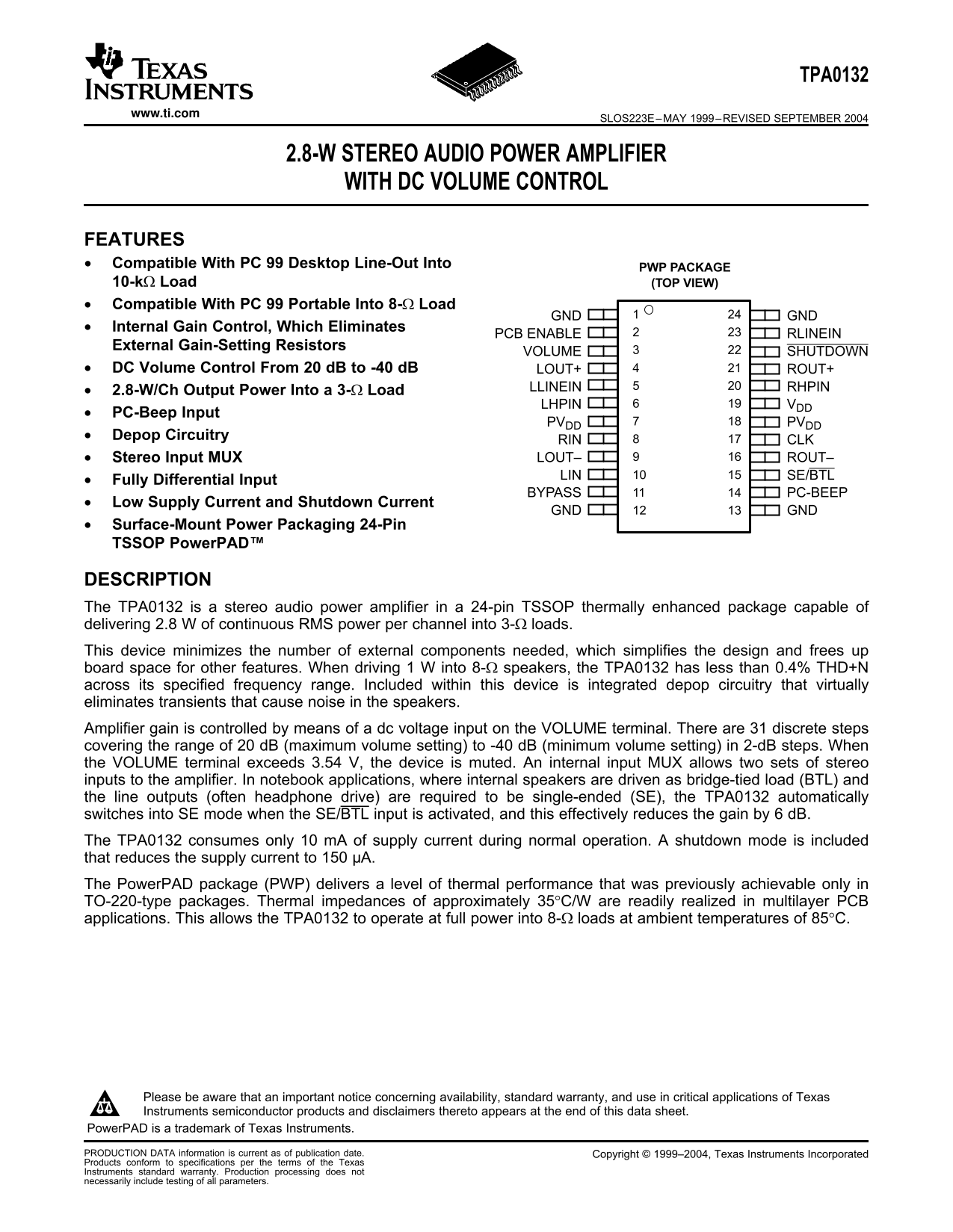
PWP PACKAGE

10-kΩ Load (TOP VIEW)

Compatible With PC Portable Into 8-Ω Load

GND GND

Internal Gain Control, Which Eliminates

PCB ENABLE RLINEIN

External Gain-Setting Resistors

VOLUME SHUTDOWN

DC Volume Control From d B to -40 d B LOUT+ ROUT+

LLINEIN RHPIN

2.8-W/Ch Output Power Into 3-Ω Load

LHPIN VDD

PC-Beep Input

PVDD PVDD

Depop Circuitry

RIN CLK Stereo Input MUX LOUT– ROUT–

LIN SE/BTL

Fully Differential Input

BYPASS PC-BEEP

Low Supply Current and Shutdown Current

GND GND

Surface-Mount Power Packaging 24-Pin

TSSOP Power PAD™

DESCRIPTION

The TPA0132 is stereo audio power amplifier in 24-pin TSSOP thermally enhanced package capable of

delivering 2.8 of continuous RMS power per channel into 3-Ω loads.

This device minimizes the number of external components needed, which simplifies the design and frees up

board space for other features. When driving into 8-Ω speakers, the TPA0132 has less than 0.4% THD+N

across its specified frequency range. Included within this device is integrated depop circuitry that virtually

eliminates transients that cause noise in the speakers.

Amplifier gain is controlled by means of dc voltage input on the VOLUME terminal. There are discrete steps

covering the range of d B (maximum volume setting) to -40 d B (minimum volume setting) in 2-d B steps. When

the VOLUME terminal exceeds 3.54 V, the device is muted. An internal input MUX allows two sets of stereo

inputs to the amplifier. In notebook applications, where internal speakers are driven as bridge-tied load (BTL) and

the line outputs (often headphone drive) are required to be single-ended (SE), the TPA0132 automatically

switches into SE mode when the SE/BTL input is activated, and this effectively reduces the gain by d B.

The TPA0132 consumes only m A of supply current during normal operation. shutdown mode is included

that reduces the supply current to µA.

The Power PAD package (PWP) delivers level of thermal performance that was previously achievable only in

TO-220-type packages. Thermal impedances of approximately 35°C/W are readily realized in multilayer PCB

applications. This allows the TPA0132 to operate at full power into 8-Ω loads at ambient temperatures of 85°C.

Please be aware that an important notice concerning availability, standard warranty, and use in critical applications of Texas

Instruments semiconductor products and disclaimers thereto appears at the end of this data sheet.

Power PAD is trademark of Texas Instruments.

PRODUCTION DATA information is current as of publication date. Copyright 1999–2004, Texas Instruments Incorporated

Products conform to specifications per the terms of the Texas

Instruments standard warranty. Production processing does not

necessarily include testing of all parameters.

Page Summary Contents For Texas Instruments TPA0132 Data Sheet

Page 1 TPA0132 www.ti.com SLOS223E–MAY 1999–REVISED SEPTEMBER 2.8-W STEREO AUDIO POWER AMPLIFIER WITH DC VOLUME CONTROL FEATURES Compatible With PC Desktop Line-Out Into PWP PACKAGE 10-kΩ Load (TOP VIEW) Com...
Page 2 TPA0132 www.ti.com SLOS223E–MAY 1999–REVISED SEPTEMBER These devices have limited built-in ESD protection. The leads should be shorted together or the device placed in conductive foam during storage o...
Page 3 TPA0132 www.ti.com SLOS223E–MAY 1999–REVISED SEPTEMBER Terminal Functions TERMINAL I/O DESCRIPTION NAME NO. BYPASS Tap to voltage divider for internal mid-supply bias generator If 47-n F capacitor is ...
Page 4 TPA0132 www.ti.com SLOS223E–MAY 1999–REVISED SEPTEMBER DISSIPATION RATING TABLE PACKAGE TA≤ 25°C DERATING FACTOR TA 70°C TA 85°C PWP 2.7 21.8 m W/°C 1.7 1.4 (1) See the Texas Instruments document, Pow...
Page 5 TPA0132 www.ti.com SLOS223E–MAY 1999–REVISED SEPTEMBER +N To ta l H ar ic is to rt io is TYPICAL CHARACTERISTICS Table of Graphs FIGURE vs Output power 1, 4, 6, 8, vs Voltage gain THD+N Total harmonic...
Page 6 TPA0132 www.ti.com SLOS223E–MAY 1999–REVISED SEPTEMBER +N To ta l H ar ic is to rt io is +N To ta l H ar ic is to rt io is TOTAL HARMONIC DISTORTION PLUS NOISE TOTAL HARMOINIC DISTORTION PLUS NOISE vs...
Page 7 TPA0132 www.ti.com SLOS223E–MAY 1999–REVISED SEPTEMBER +N To ta l H ar ic is to rt io is +N To ta l H ar ic is to rt io is TOTAL HARMONIC DISTORTION PLUS NOISE TOTAL HARMONIC DISTORTION PLUS NOISE vs ...
Page 8 TPA0132 www.ti.com SLOS223E–MAY 1999–REVISED SEPTEMBER tp t N is lta Vµ +N To ta l H ar ic is to rt io is TOTAL HARMONIC DISTORTION PLUS NOISE TOTAL HARMONIC DISTORTION PLUS NOISE vs vs FREQUENCY OUTP...
Page 9 TPA0132 www.ti.com SLOS223E–MAY 1999–REVISED SEPTEMBER ro ss ta lk ly ip le ej ec tio at io SUPPLY RIPPLE REJECTION RATIO CROSSTALK vs vs FREQUENCY FREQUENCY -40 RL = 32 Ω PO = 1 W C(BYP) = 0.47 µF -5...
Page 10 TPA0132 www.ti.com SLOS223E–MAY 1999–REVISED SEPTEMBER ai td tt en at io SHUTDOWN ATTENUATION SIGNAL-TO-NOISE RATIO vs vs FREQUENCY FREQUENCY VI = 1 VRMS PO = 1 W RL = 8 Ω BTL RL = 10 kΩ, SE AV = 20 d...
Page 11 TPA0132 www.ti.com SLOS223E–MAY 1999–REVISED SEPTEMBER - P er is si at io tp er OUTPUT POWER OUTPUT POWER vs vs LOAD RESISTANCE LOAD RESISTANCE AV = 20 to 0 d B AV = 14 to 0 d B BTL SE 10% THD+N 10% T...
Page 12 TPA0132 www.ti.com SLOS223E–MAY 1999–REVISED SEPTEMBER - P er is si at io POWER DISSIPATION INPUT IMPEDANCE vs vs AMBIENT TEMPERATURE GAIN ΘJA1 = 45.9°C/W ΘJA2 = 45.2°C/W ΘJA3 = 31.2°C/W ΘJA4 = 18.6°C...
Page 13 TPA0132 www.ti.com SLOS223E–MAY 1999–REVISED SEPTEMBER Volume Control Characteristics Table 1. Typical DC Volume Control VOLUME (Terminal 3) TYPICAL VOLTAGE INCREASING VOLTAGE GAIN of AMPLIFIER OR FIX...
Page 14 TPA0132 www.ti.com SLOS223E–MAY 1999–REVISED SEPTEMBER GAIN HISTOGRAM AT d B re en cy f O cc ra ce Gain − d B Figure 29. Typical Gain Variance
Page 15 TPA0132 www.ti.com SLOS223E–MAY 1999–REVISED SEPTEMBER APPLICATION INFORMATION COMPONENT SELECTION Figure and Figure are schematic diagrams of typical notebook computer application circuits. CIRHP Hea...
Page 16 TPA0132 www.ti.com SLOS223E–MAY 1999–REVISED SEPTEMBER APPLICATION INFORMATION (continued) CIRHP− 0.47 µF RHPIN CIRIN− 32-Step 0.47 µF Volume Negative RLINEIN Control Differential Input Signal ROUT+ C...
Page 17 TPA0132 www.ti.com SLOS223E–MAY 1999–REVISED SEPTEMBER APPLICATION INFORMATION (continued) VOLUME CONTROL OPERATION The VOLUME pin controls the volume of the TPA0132. It is controlled with dc voltage,...
Page 18 TPA0132 www.ti.com SLOS223E–MAY 1999–REVISED SEPTEMBER APPLICATION INFORMATION (continued) CR Ri To increase filter accuracy, increase the value of the capacitor and decrease the value of the resisto...
Page 19 TPA0132 www.ti.com SLOS223E–MAY 1999–REVISED SEPTEMBER APPLICATION INFORMATION (continued) OUTPUT COUPLING CAPACITOR, C(C) In typical single-supply SE configuration, an output coupling capacitor (C(C)...
Page 20 TPA0132 www.ti.com SLOS223E–MAY 1999–REVISED SEPTEMBER BRIDGED-TIED LOAD VS SINGLE-ENDED MODE Figure shows Class-AB audio power amplifier (APA) in BTL configuration. The TPA0132 amplifier consists of ...
Page 21 TPA0132 www.ti.com SLOS223E–MAY 1999–REVISED SEPTEMBER VO(PP) VO(PP) Figure 35. Single-Ended Configuration and Frequency Response Increasing power to the load does carry penalty of increased internal ...
Page 22 TPA0132 www.ti.com SLOS223E–MAY 1999–REVISED SEPTEMBER Efficiency of BTL amplifier Where: VLrms2 VP VP PL and VLRMS therefore, PL RL 2RL VP VP 2VP PSUP VDD IDDavg IDDavg sin(t) dt [cos(t)] and and RL ...
Page 23 TPA0132 www.ti.com SLOS223E–MAY 1999–REVISED SEPTEMBER CREST FACTOR AND THERMAL CONSIDERATIONS Class-AB power amplifiers dissipate significant amount of heat in the package under normal operating cond...
Page 24 TPA0132 www.ti.com SLOS223E–MAY 1999–REVISED SEPTEMBER Table 5. TPA0132 Power Rating, 5-V, 8-Ω Stereo PEAK OUTPUT POWER POWER DISSIPATION MAXIMUM AMBIENTAVERAGE OUTPUT POWER(W) (W/Channel) TEMPERATURE...
Page 25 TPA0132 www.ti.com SLOS223E–MAY 1999–REVISED SEPTEMBER SE/BTL OPERATION The ability of the TPA0132 to easily switch between BTL and SE modes is one of its most important cost-saving features. This fea...
Page 26 TPA0132 www.ti.com SLOS223E–MAY 1999–REVISED SEPTEMBER PC-BEEP OPERATION The PC-BEEP input allows system beep to be sent directly from computer through the amplifier to the speakers with few external ...
Page 27 PACKAGE OPTION ADDENDUM www.ti.com 18-Apr-2006 PACKAGING INFORMATION Orderable Device Status Package Package Pins Package Eco Plan Lead/Ball Finish MSL Peak Temp Type Drawing Qty TPA0132PWP ACTIVE HTS...
Page 31 IMPORTANT NOTICE Texas Instruments Incorporated and its subsidiaries (TI) reserve the right to make corrections, modifications, enhancements, improvements, and other changes to its products and servic...

Manual Details

Brand Texas Instruments
Pages 31
File Size 735.76 KB
Published June 22, 2026
1 views

Enter the captcha to get the download link:

captcha

Frequently Asked Questions

What is the maximum continuous power output per channel?

The TPA0132 can deliver 2.8 W of continuous RMS power per channel into 3-Ω loads.

How does the device manage different speaker loading modes (SE/BTL)?

When the SE/BTL input is activated, the amplifier automatically switches to single-ended (SE) mode, which reduces the gain by 6 dB.

What are the steps and range of volume control?

The DC Volume Control offers 31 discrete steps across a range from 20 dB (maximum) down to -40 dB (minimum), in 2-dB increments.

What safety precautions should be taken during handling?

Due to limited built-in ESD protection, leads should be shorted together or the device placed in conductive foam for storage and handling.