# A B C D E F G H I J K L M N O P Q R S T U V W X Y Z

Texas Instruments TLV2370 Data Sheet

Summary

The TLV237x series offers single-supply operational amplifiers featuring robust rail-to-rail input/output capability. The manual provides comprehensive details on these high-performance devices, highlighting their ability to operate over extended industrial temperature ranges and low voltages (down to 2.7V). Ideal for battery-powered or sensor interface designs requiring minimal power consumption and high bandwidth, this family is perfect for engineers developing highly reliable, portable analog circuits that demand exceptional performance from sources like Li-Ion batteries and modern microcontrollers.
📄 Preview PAGE OF 28

Page 1 Text Content

查询TLV2370供应商

SLOS270C − MARCH 2001 − REVISED DECEMBER 2003

Rail-To-Rail Input/Output

Operational Amplifier

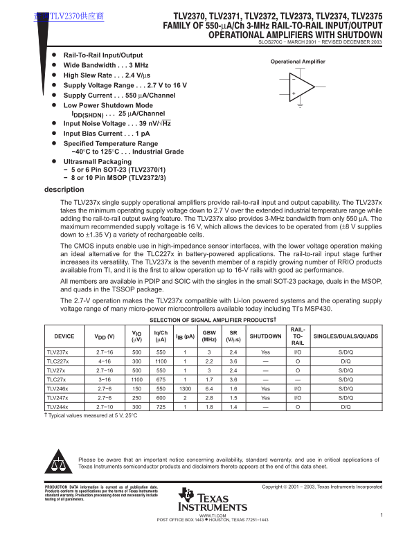
Wide Bandwidth 3 MHz High Slew Rate 2.4 V/µs Supply Voltage Range 2.7 V to 16 V Supply Current 550 µA/Channel Low Power Shutdown Mode IDD(SHDN) 25 µA/Channel Input Noise Voltage 39 n V/√Hz Input Bias Current 1 p A Specified Temperature Range −40°C to 125°C Industrial Grade Ultrasmall Packaging − 5 or 6 Pin SOT-23 (TLV2370/1) − 8 or 10 Pin MSOP (TLV2372/3) description The TLV237x single supply operational amplifiers provide rail-to-rail input and output capability. The TLV237x takes the minimum operating supply voltage down to 2.7 V over the extended industrial temperature range while adding the rail-to-rail output swing feature. The TLV237x also provides 3-MHz bandwidth from only 550 µA. The maximum recommended supply voltage is 16 V, which allows the devices to be operated from (±8 V supplies down to ±1.35 V) a variety of rechargeable cells. The CMOS inputs enable use in high-impedance sensor interfaces, with the lower voltage operation making an ideal alternative for the TLC227x in battery-powered applications. The rail-to-rail input stage further increases its versatility. The TLV237x is the seventh member of a rapidly growing number of RRIO products available from TI, and it is the first to allow operation up to 16-V rails with good ac performance. All members are available in PDIP and SOIC with the singles in the small SOT-23 package, duals in the MSOP, and quads in the TSSOP package. The 2.7-V operation makes the TLV237x compatible with Li-Ion powered systems and the operating supply voltage range of many micro-power microcontrollers available today including TI’s MSP430.

SELECTION OF SIGNAL AMPLIFIER PRODUCTS†

RAIL-

VIO Iq/Ch GBW SR

DEVICE VDD (V) IIB (p A) SHUTDOWN TO- SINGLES/DUALS/QUADS

(µV) (µA) (MHz) (V/µs)

TLV237x 2.7−16 2.4 Yes I/O S/D/Q TLC227x 4−16 2.2 3.6 D/Q TLV27x 2.7−16 2.4 S/D/Q TLC27x 3−16 1.7 3.6 S/D/Q TLV246x 2.7−6 6.4 1.6 Yes I/O S/D/Q TLV247x 2.7−6 2.8 1.5 Yes I/O S/D/Q TLV244x 2.7−10 1.8 1.4 D/Q Typical values measured at 5 V, 25°C

Please be aware that an important notice concerning availability, standard warranty, and use in critical applications of Texas Instruments semiconductor products and disclaimers thereto appears at the end of this data sheet.

!"#$%&'(!$" !) *+%%,"( ') $# -+./!*'(!$" 0'(,1 Copyright  2001 − 2003, Texas Instruments Incorporated

1WWW.TI.COM

POST OFFICE BOX 1443 • HOUSTON, TEXAS 77251−1443

Page Summary Contents For Texas Instruments TLV2370 Data Sheet

Page 1 查询TLV2370供应商 SLOS270C − MARCH 2001 − REVISED DECEMBER 2003 Rail-To-Rail Input/Output Operational Amplifier Wide Bandwidth 3 MHz High Slew Rate 2.4 V/µs Supply Voltage Range 2.7 V to 16 V Supply Curren...
Page 2 SLOS270C − MARCH 2001 − REVISED DECEMBER 2003 FAMILY PACKAGE TABLE NUMBER OF PACKAGE TYPES UNIVERSAL DEVICE SHUTDOWN CHANNELS PDIP SOIC SOT-23 TSSOP MSOP EVM BOARD TLV2370 Yes TLV2371 Refer to the EVM...
Page 3 SLOS270C − MARCH 2001 − REVISED DECEMBER 2003 TLV237x PACKAGE PINOUTS(1) TLV2370 TLV2370 TLV2371 DBV PACKAGE D OR P PACKAGE DBV PACKAGE (TOP VIEW) (TOP VIEW) (TOP VIEW) 1OUT VDD NC SHDN 1OUT VDD IN− V...
Page 4 SLOS270C − MARCH 2001 − REVISED DECEMBER 2003 absolute maximum ratings over operating free-air temperature range (unless otherwise noted)† Supply voltage, VDD (see Note 1) 16.5 V. . . . . . . . . . . ...
Page 5 SLOS270C − MARCH 2001 − REVISED DECEMBER 2003 electrical characteristics at specified free-air temperature, VDD = 2.7 V, 5 V, and 15 V (unless otherwise noted) dc performance PARAMETER TEST CONDITIONS...
Page 6 SLOS270C − MARCH 2001 − REVISED DECEMBER 2003 electrical characteristics at specified free-air temperature, VDD = 2.7 V, 5 V, and 15 V (unless otherwise noted) (continued) output characteristics PARAM...
Page 7 SLOS270C − MARCH 2001 − REVISED DECEMBER 2003 electrical characteristics at specified free-air temperature, VDD = 2.7 V, 5 V, and 15 V (unless otherwise noted) (continued) dynamic performance PARAMETE...
Page 8 SLOS270C − MARCH 2001 − REVISED DECEMBER 2003 TYPICAL CHARACTERISTICS Table of Graphs FIGURE VIO Input offset voltage vs Common-mode input voltage 1, 2, 3 CMRR Common-mode rejection ratio vs Frequency...
Page 9 SLOS270C − MARCH 2001 − REVISED DECEMBER 2003 -M ej ec ti at io IO In ff se Vo lt ag Vµ ig -L ev el tp Vo lt ag TYPICAL CHARACTERISTICS INPUT OFFSET VOLTAGE INPUT OFFSET VOLTAGE INPUT OFFSET VOLTAGE v...
Page 10 -L ev el tp Vo lt ag SLOS270C − MARCH 2001 − REVISED DECEMBER 2003 TYPICAL CHARACTERISTICS LOW-LEVEL OUTPUT VOLTAGE HIGH-LEVEL OUTPUT VOLTAGE PEAK-TO-PEAK OUTPUT VOLTAGE ly rr en /C vs vs vs if fe re ...
Page 11 SLOS270C − MARCH 2001 − REVISED DECEMBER 2003 le at TYPICAL CHARACTERISTICS SLEW RATE SLEW RATE PHASE MARGIN vs vs SUPPLY VOLTAGE FREE-AIR TEMPERATURE In Vo lt ag iv al en In is Vo lt ag CAPACITIVE LO...
Page 12 td rw ar ev er se Is la ti SLOS270C − MARCH 2001 − REVISED DECEMBER 2003 TYPICAL CHARACTERISTICS INVERTING LARGE-SIGNAL RESPONSE INVERTING LARGE-SIGNAL RESPONSE In Vo lt ag In Vo lt ag VDD = 5 V VDD =...
Page 13 SLOS270C − MARCH 2001 − REVISED DECEMBER 2003 ly rr en /C tp Vo lt ag td ls TYPICAL CHARACTERISTICS SHUTDOWN SUPPLY CURRENT/OUTPUT VOLTAGE SHUTDOWN SUPPLY CURRENT/OUTPUT VOLTAGE vs vs TIME TIME VDD = ...
Page 14 SLOS270C − MARCH 2001 − REVISED DECEMBER 2003 APPLICATION INFORMATION rail-to-rail input operation The TLV237x input stage consists of two differential transistor pairs, NMOS and PMOS, that operate to...
Page 15 SLOS270C − MARCH 2001 − REVISED DECEMBER 2003 APPLICATION INFORMATION general configurations When receiving low-level signals, limiting the bandwidth of the incoming signals into the system is often r...
Page 16 SLOS270C − MARCH 2001 − REVISED DECEMBER 2003 APPLICATION INFORMATION circuit layout considerations To achieve the levels of high performance of the TLV237x, follow proper printed-circuit board design...
Page 17 SLOS270C − MARCH 2001 − REVISED DECEMBER 2003 APPLICATION INFORMATION general power dissipation considerations For a given θJA, the maximum power dissipation is shown in Figure 37 and is calculated by...
Page 18 MECHANICAL DATA MPDI001A – JANUARY 1995 – REVISED JUNE 1999 P (R-PDIP-T8) PLASTIC DUAL-IN-LINE 0.070 (1,78) MAX 0.020 (0,51) MIN Gage Plane 0.200 (5,08) MAX Seating Plane 0.010 (0,25) NOM 0.125 (3,18)...
Page 27 MECHANICAL DATA MTSS001C – JANUARY 1995 – REVISED FEBRUARY 1999 PW (R-PDSO-G**) PLASTIC SMALL-OUTLINE PACKAGE 14 PINS SHOWN 0,15 NOM Gage Plane Seating Plane 1,20 MAX 0,10 PINS ** DIM A MAX 3,10 5,10 ...
Page 28 IMPORTANT NOTICE Texas Instruments Incorporated and its subsidiaries (TI) reserve the right to make corrections, modifications, enhancements, improvements, and other changes to its products and servic...

Manual Details

Brand Texas Instruments
Pages 28
File Size 864.82 KB
Published June 17, 2026
2 views

Enter the captcha to get the download link:

captcha

Frequently Asked Questions

What is the operating temperature range for the TLV237x amplifier?

The specified operating temperature range is from -40°C to 125°C, which classifies it as Industrial Grade.

Which microcontrollers are compatible with this device's low voltage operation?

It is compatible with Li-Ion powered systems and many micro-power microcontrollers, including the TI’s MSP430.

What is the maximum recommended supply voltage for use?

The maximum recommended supply voltage is 16 V.

How can I minimize power consumption when not actively transmitting signals?

The device features Low Power Shutdown Mode I, which draws a current of only 25 µA per channel.