Texas Instruments TLC5922 Specifications and User Guide
Summary
This high-performance 16-channel constant-current sink LED driver is engineered for sophisticated illumination applications, supporting monocolor, multicolor, and full-color displays from 0 to 80 mA. It offers granular control via SPI compatibility, enabling individual dot correction and On/Off state management across all channels. The accompanying technical manual provides complete design guidelines, featuring functional block diagrams, absolute maximum ratings, and detailed electrical characteristics needed by hardware engineers and lighting designers building reliable, high-density LED signage or display backlighting systems.
Page 1 Text Content
TLC5922
www.ti.com
SLVS486A–SEPTEMBER 2003–REVISED MARCH
LED DRIVER
FEATURES Controlled In-Rush Current
Channels
APPLICATIONS
Drive Capability
Monocolor, Multicolor, Fullcolor LED Display–
to m A (Constant-Current Sink)
Monocolor, Multicolor LED Signboard
Constant Current Accuracy
Display Backlighting
±1% (typical)
Multicolor LED Lighting Applications
Serial Data Interface, SPI Compatible
Fast Switching Output: Tr Tf 10ns (typical) DESCRIPTION
CMOS Level Input/Output
The TLC5922 is 16-channel constant-current sink
MHz Data Transfer Rate driver. Each channel has an On/Off state and
128-step adjustable constant-current sink (dot correc-•
VCC 3.0 to 5.5
tion). The dot correction adjusts the brightness vari-
Operating Temperature –20°C to °C
ations between LED, LED channels, and other LED
LED Supply Voltage up to drivers. Both dot correction and On/Off state are
accessible via serial data interface. single exter-•
32-pin HTSSOP (Power PAD™) Package
nal resistor sets the maximum current of all 16•
Dot Correction
channels.
bit (128 Steps)
Individually Adjustable For Each Channel
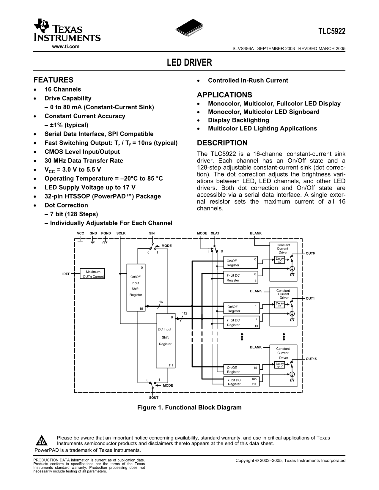
GNDVCC PGND SINSCLK XLATMODE BLANK
MODE Constant Current Driver OUT0 Delay
On/Off x0 Register
Maximum
OUTn Current 7−bit DC
On/Off
Register
Input Shift
BLANK Constant Register Current Driver OUT1 Delay On/Off x1
Register
7−bit DC Register
DC Input
Shift Register
BLANK
Constant Current Driver OUT15 Delay On/Off x15
Register
7−bit DC Register
Figure 1. Functional Block Diagram
Please be aware that an important notice concerning availability, standard warranty, and use in critical applications of Texas
Instruments semiconductor products and disclaimers thereto appears at the end of this data sheet.
Power PAD is trademark of Texas Instruments.
PRODUCTION DATA information is current as of publication date. Copyright 2003–2005, Texas Instruments Incorporated
Products conform to specifications per the terms of the Texas
Instruments standard warranty. Production processing does not
necessarily include testing of all parameters.
Page Summary Contents For Texas Instruments TLC5922 Specifications and User Guide
Manual Details
| Brand | Texas Instruments |
|---|---|
| Pages | 16 |
| File Size | 383.28 KB |
| Published | July 22, 2026 |
Enter the captcha to get the download link:

Frequently Asked Questions
Does this driver include brightness correction for LEDs?
Yes, it offers dot correlation through 7-bit (128 steps) individual adjustment capability for each channel.
What steps must be taken during storage or handling of the device?
Due to limited built-in ESD protection, leads must be shorted together or the device placed in conductive foam.
What is the constant current output range per channel?
The channels support an adjustable constant-current sink ranging from 0 mA up to 80 mA.
How can I control the various functions of this driver?
Control is achieved via a serial data interface that is compatible with SPI and manages On/Off states and dot correction.