Texas Instruments SN54F02, SN74F02 User Guide and Manual
Summary
Implement reliable digital logic circuits with these high-performance quad two-input NOR gates. The comprehensive manual serves as a critical resource for electronics engineers and circuit designers, detailing operational specifications for integration into complex systems. It covers essential information including functional logic diagrams across multiple package types (e.g., DIP, SOIC), detailed electrical characteristics, absolute maximum ratings, and defined operating temperature ranges from industrial military grades to commercial use.
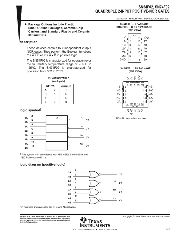
Page 1 Text Content
SN54F02, SN74F02
QUADRUPLE 2-INPUT POSITIVE-NOR GATES
SDFS036A – MARCH 1987 – REVISED OCTOBER 1993
Package Options Include Plastic SN54F02 J PACKAGE SN74F02 D OR N PACKAGE
Small-Outline Packages, Ceramic Chip
(TOP VIEW)
Carriers, and Standard Plastic and Ceramic 300-mil DIPs
1Y VCC
description
These devices contain four independent 2-input 2Y 4A NOR gates. They perform the Boolean functions 2A 3Y Y = A + B or Y = A • B in positive logic. 2B 3B
GND 3A
The SN54F02 is characterized for operation over the full military temperature range of –55°C to 125°C. The SN74F02 is characterized for SN54F02 FK PACKAGE
operation from 0°C to 70°C. (TOP VIEW)
FUNCTION TABLE (each gate)
INPUTS OUTPUT 1B 4B
NC NC 2Y 4A NC NC 2A 3Y
logic symbol†
1A ≥1 NC – No internal connection
This symbol is in accordance with ANSI/IEEE Std 91-1984 and IEC Publication 617-12.
logic diagram (positive logic)
Pin numbers shown are for the D, J, and N packages.
PRODUCTION DATA information is current as of publication date. Copyright 1993, Texas Instruments Incorporated
Products conform to specifications per the terms of Texas Instruments standard warranty. Production processing does not necessarily include testing of all parameters.
2–1POST OFFICE BOX 655303 • DALLAS, TEXAS 75265
Page Summary Contents For Texas Instruments SN54F02, SN74F02 User Guide and Manual
Manual Details
| Brand | Texas Instruments |
|---|---|
| Pages | 15 |
| File Size | 641.87 KB |
| Published | June 05, 2026 |
Enter the captcha to get the download link:

Frequently Asked Questions
What is the operating temperature range for SN54F02 and SN74F02?
SN54F02 operates from –55°C to 125°C, while SN74F02 operates from 0°C to 70°C.
How do I calculate the logical output for these gates?
They perform positive-NOR logic functions Y = A + B or Y = A • B.
What are the voltage requirements for operation?
The recommended supply voltage range (VCC) is 4.5V to 5.5V, with an input voltage range of –1.2V to 7V.
Is there a difference in storage temperature between models?
SN54F02 and SN74F02 both have a comparable storage temperature range of –65°C to 150°C.