Texas Instruments SLLS563B Data Sheet
Summary
These differential transceivers provide reliable, high-speed communication for industrial automation across twisted-pair networks. Optimized for PROFIBUS and RS-485 standards, they are essential components for factory environments, including chemical processing, automotive production, and HVAC systems. The manual details robust data transmission capabilities up to 40 Mbps, paired with fail-safe receiving logic, high ESD protection (10kV HBM), and thermal shutdown mechanisms, guaranteeing resilient operation in critical industrial control applications.
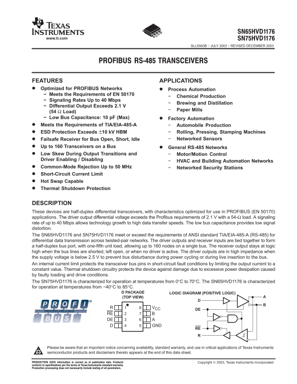
Page 1 Text Content
www.ti.com
SLLS563B − JULY 2003 − REVISED DECEMBER 2003
FEATURES APPLICATIONS Optimized for PROFIBUS Networks Process Automation − Meets the Requirements of EN 50170
Chemical Production
− Signaling Rates Up to 40 Mbps
Brewing and Distillation
− Differential Output Exceeds 2.1 V
Paper Mills
(54 Ω Load) − Low Bus Capacitance: 10 p F (Max) Factory Automation Meets the Requirements of TIA/EIA-485-A Automobile Production ESD Protection Exceeds ±10 k V HBM Rolling, Pressing, Stamping Machines
Failsafe Receiver for Bus Open, Short, Idle Networked Sensors
Up to 160 Transceivers on a Bus General RS-485 Networks Low Skew During Output Transitions and Motor/Motion Control Driver Enabling / Disabling
HVAC and Building Automation Networks
Common-Mode Rejection Up to 50 MHz Networked Security Stations Short-Circuit Current Limit Hot Swap Capable Thermal Shutdown Protection
DESCRIPTION These devices are half-duplex differential transceivers, with characteristics optimized for use in PROFIBUS (EN 50170) applications. The driver output differential voltage exceeds the Profibus requirements of 2.1 V with a 54-Ω load. A signaling rate of up to 40 Mbps allows technology growth to high data transfer speeds. The low bus capacitance provides low signal distortion. The SN65HVD1176 and SN75HVD1176 meet or exceed the requirements of ANSI standard TIA/EIA-485-A (RS-485) for differential data transmission across twisted-pair networks. The driver outputs and receiver inputs are tied together to form a half-duplex bus port, with one-fifth unit load, allowing up to 160 nodes on a single bus. The receiver output stays at logic high when the bus lines are shorted, left open, or when no driver is active. The driver outputs are in high impedance when the supply voltage is below 2.5 V to prevent bus disturbance during power cycling or during live insertion to the bus. An internal current limit protects the transceiver bus pins in short-circuit fault conditions by limiting the output current to a constant value. Thermal shutdown circuitry protects the device against damage due to excessive power dissipation caused by faulty loading and drive conditions. The SN75HVD1176 is characterized for operation at temperatures from 0°C to 70°C. The SN65HVD1176 is characterized for operation at temperatures from −40°C to 85°C.
D PACKAGE LOGIC DIAGRAM (POSITIVE LOGIC) (TOP VIEW)
RE DE
Please be aware that an important notice concerning availability, standard warranty, and use in critical applications of Texas Instruments semiconductor products and disclaimers thereto appears at the end of this data sheet.
Page Summary Contents For Texas Instruments SLLS563B Data Sheet
Manual Details
| Brand | Texas Instruments |
|---|---|
| Pages | 16 |
| File Size | 242.08 KB |
| Published | June 21, 2026 |
Enter the captcha to get the download link:

Frequently Asked Questions
Which model is designed for colder operating environments?
The SN65HVD1176 is characterized for operation at temperatures from −40°C to 85°C.
What protection features are included for fault conditions?
It includes internal current limits, thermal shutdown circuitry, and ESD protection (up to ±10 kV HBM).
How does the device behave if the network bus is open, shorted, or idle?
The receiver output remains at logic high under these failure conditions.
What networking standards are supported by this transceiver?
It supports PROFIBUS (EN 50170) and meets TIA/EIA-485-A standards for RS-485.