Texas Instruments PT6400 Series Data Sheet User Manual
Summary
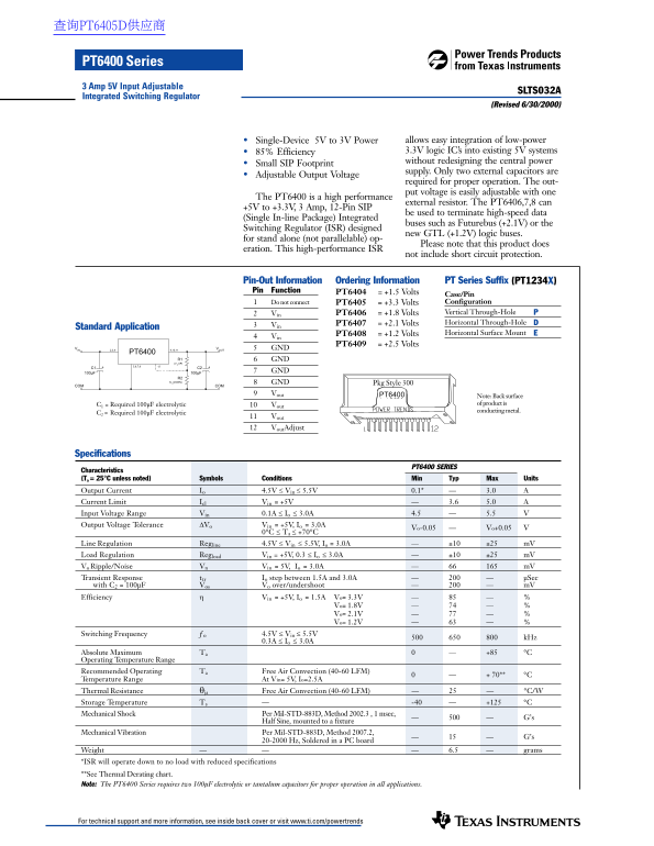
The PT6400 Series are high-performance integrated switching regulators designed for embedding low-power logic ICs into existing 5V systems. They provide efficient and reliable voltage conversion, allowing precise power stepping down (e.g., 5V to 3.3V) with a compact footprint. This technical manual is essential for electronics designers and engineers planning system upgrades, offering detailed operational specifications, current/voltage tolerance graphs, efficiency curves, thermal derating data, and guidelines crucial for optimal network integration.
Page 1 Text Content
查询PT6405D供应商
PT6400 Series 3 Amp 5V Input Adjustable
SLTS032A
Integrated Switching Regulator
(Revised 6/30/2000)
Single-Device 5V to 3V Power allows easy integration of low-power 85% Efficiency 3.3V logic IC’s into existing 5V systems without redesigning the central power
Small SIP Footprint
supply. Only two external capacitors are
Adjustable Output Voltage
required for proper operation. The out- put voltage is easily adjustable with one
The PT6400 is a high performance
external resistor. The PT6406,7,8 can
+5V to +3.3V, 3 Amp, 12-Pin SIP
be used to terminate high-speed data
(Single In-line Package) Integrated
buses such as Futurebus (+2.1V) or the
Switching Regulator (ISR) designed
new GTL (+1.2V) logic buses.
for stand alone (not parallelable) op-
Please note that this product does
eration. This high-performance ISR
not include short circuit protection.
Pin-Out Information Ordering Information PT Series Suffix (PT1234X) Pin Function PT6404 = +1.5 Volts
Case/Pin Do not connect PT6405 = +3.3 Volts Configuration Vin PT6406 = +1.8 Volts Vertical Through-Hole PT6407 = +2.1 Volts Horizontal Through-Hole
Standard Application
PT6408 = +1.2 Volts Horizontal Surface Mount
PT6409 = +2.5 Volts
VIN 9,10,11 VOUT2,3,4 GND
PT6400
R1 GND (V UP)
100µF 100µF GND
R2 (V DOWN) GND Pkg Style 300
COM COM
Vout PT6400
Note: Back surface C1 = Required 100µF electrolytic Vout of product is conducting metal.
C2 = Required 100µF electrolytic
Vout Vout Adjust
Specifications
PT6400 SERIES
Characteristics (Ta = 25°C unless noted) Symbols Conditions Min Typ Max Units Output Current Io 4.5V ≤ Vin ≤ 5.5V 0.1* 3.0 Current Limit Icl Vin = +5V 3.6 5.0 Input Voltage Range Vin 0.1A ≤ Io ≤ 3.0A 4.5 5.5 Output Voltage Tolerance ∆Vo Vin = +5V, Io = 3.0A
Vo-0.05 Vo+0.05 V0°C ≤ Ta ≤ +70°C
Line Regulation Regline 4.5V ≤ Vin ≤ 5.5V, Io = 3.0A ±10 ±25 m V Load Regulation Regload Vin = +5V, 0.3 ≤ Io ≤ 3.0A ±10 ±25 m V Vo Ripple/Noise Vn Vin = 5V, Io = 3.0A m V Transient Response ttr Io step between 1.5A and 3.0A µSec with C2 = 100µF Vos Vo over/undershoot m V Efficiency Vin = +5V, Io = 1.5A Vo= 3.3V
Vo= 1.8V Vo= 2.1V Vo= 1.2V
Switching Frequency ƒo 4.5V ≤ Vin ≤ 5.5V
k Hz0.3A ≤ Io ≤ 3.0A
Absolute Maximum Ta +85 °C Operating Temperature Range Recommended Operating Ta Free Air Convection (40-60 LFM)
+ 70** °CTemperature Range
At Vin= 5V, Io=2.5A
Thermal Resistance θja Free Air Convection (40-60 LFM) °C/W Storage Temperature Ts -40 +125 °C Mechanical Shock Per Mil-STD-883D, Method 2002.3 , 1 msec,
G’s Half Sine, mounted to a fixture
Mechanical Vibration Per Mil-STD-883D, Method 2007.2,
20-2000 Hz, Soldered in a PC board
Weight 6.5 grams *ISR will operate down to no load with reduced specifications **See Thermal Derating chart. Note: The PT6400 Series requires two 100µF electrolytic or tantalum capacitors for proper operation in all applications.
For technical support and more information, see inside back cover or visit www.ti.com/powertrends
Page Summary Contents For Texas Instruments PT6400 Series Data Sheet User Manual
Manual Details
| Brand | Texas Instruments |
|---|---|
| Pages | 6 |
| File Size | 120.48 KB |
| Published | June 15, 2026 |
Enter the captcha to get the download link:
