Texas Instruments DEM-PCM3500 Data Sheet
Summary
The DEM-PCM3500 Evaluation Board enables engineers to quickly prototype and test MODEM/VOICE CODEC systems utilizing the PCM3500 single-channel codec. This manual provides extensive guidance on setting up your hardware, detailing board schematics, power supply necessities (+2.7V to +3.6V), and function of DIP switches for advanced configuration (e.g., Time Slot or Master mode). Ideal for developers requiring rapid evaluation of Analog Front End circuits and serial interface operation in voice communication applications.
Page 1 Text Content
查询DEM-PCM3500供应商
DEM-PCM3500
EVALUATION BOARD
INSTRUCTION MANUAL
FEATURES DESCRIPTION EVALUATION BOARD FOR THE PCM3500 The DEM-PCM3500 is a simple evaluation board for MODEM/VOICE CODEC the PCM3500 single-channel CODEC. It is designed
for quick evaluation of the PCM3500 features and
DIP SWITCH FOR SETTING HARDWARE
performance. A prototype area allows for external
MODE CONTROLS
analog input and output circuitry to be mounted di-
CONNECTORS FOR SERIAL INTERFACE,
rectly on the evaluation board.
SYSTEM CLOCK, ANALOG INPUT/OUTPUT, AND POWER SUPPLIES PROTOTYPE AREA FOR BUILDING ANA- LOG FRONT END (AFE) CIRCUITS SINGLE POWER SUPPLY: +2.7V to +3.6V
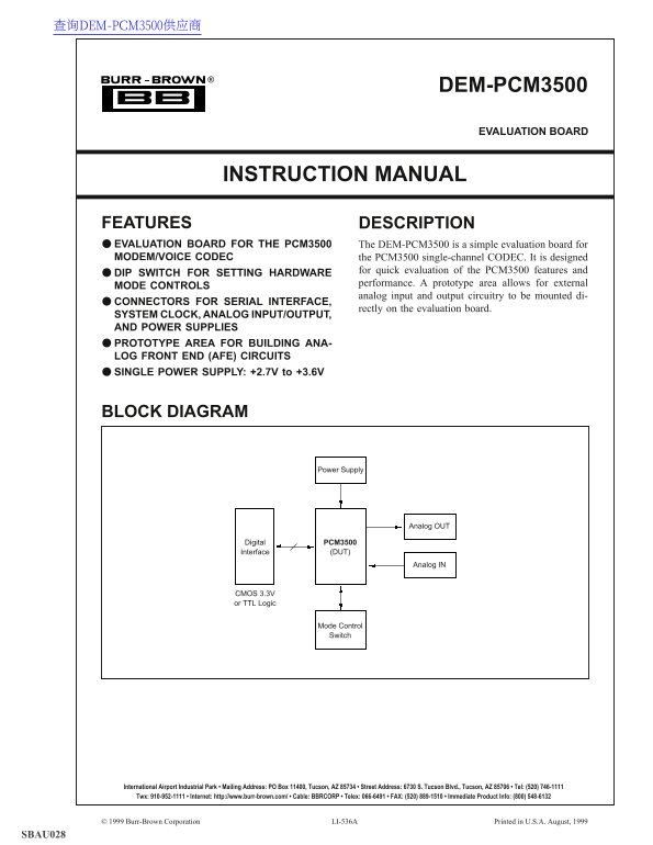
BLOCK DIAGRAM
Power Supply
Analog OUT
Digital PCM3500 Interface (DUT)
Analog IN
CMOS 3.3V or TTL Logic
Mode Control Switch
International Airport Industrial Park • Mailing Address: PO Box 11400, Tucson, AZ 85734 • Street Address: 6730 S. Tucson Blvd., Tucson, AZ 85706 • Tel: (520) 746-1111 Twx: 910-952-1111 • Internet: http://www.burr-brown.com/ • Cable: BBRCORP • Telex: 066-6491 • FAX: (520) 889-1510 • Immediate Product Info: (800) 548-6132
© 1999 Burr-Brown Corporation LI-536A Printed in U.S.A. August, 1999
SBAU028
Page Summary Contents For Texas Instruments DEM-PCM3500 Data Sheet
Manual Details
| Brand | Texas Instruments |
|---|---|
| Pages | 4 |
| File Size | 42.97 KB |
| Published | June 17, 2026 |
Enter the captcha to get the download link:

Frequently Asked Questions
What is the required power supply voltage for the DEM-PCM3500?
The +V pin can be set in a range between +2.7V and +3.6V.
How must I configure the crystal oscillator clocking circuit?
A resonant crystal is recommended, with load capacitors (C) set within the range of 10pF – 33pF.
Where do I adjust the operational modes for hardware performance?
Hardware performance is adjusted using dedicated DIP switches, such as SW1, to enable or disable features like PWDN or LOOP.
What dictates the connection for BCK and FS if I use Slave mode?
When in Slave mode, the signals for BCK and FS must be derived from the SCKIO connector pins.