Texas Instruments DEM-DAI1742 Data Sheet
Summary
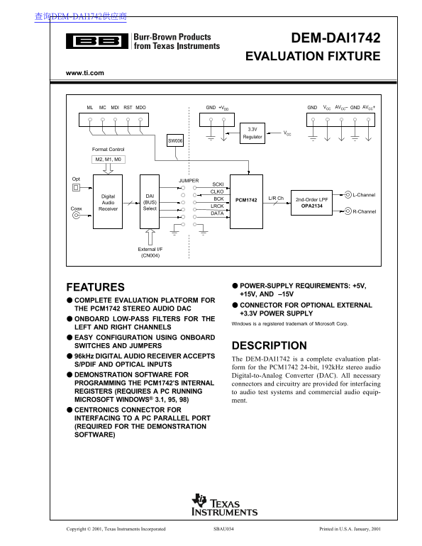
The DEM-DAI1742 is a comprehensive evaluation fixture designed for developers integrating the PCM1742 24-bit, 192kHz stereo audio DAC into high-end audio test systems. This robust platform offers multiple power supplies and fully configurable outputs (S/PDIF, OPTICAL, L/R analog) with integrated low-pass filters. The manual provides detailed instructions on setup, including required jumper settings, operational controls (such as attenuation levels and oversampling rates), and troubleshooting for engineers building professional audio demonstration boards.
Page 1 Text Content
查询DEM-DAI1742供应商
DEM-DAI1742 EVALUATION FIXTURE
www.ti.com
MC MDI RST MDO GND +VDD GND VCC AVCC– GNDML AVCC+
Regulator
SW006
Format Control
JUMPER
SCKI CLKO
DAI L-Channel
Digital
BCK L/R Ch
PCM1742 2nd-Order LPF
Audio (BUS)
LRCK OPA2134
Coax Receiver Select
R-Channel
External I/F (CN004)
POWER-SUPPLY REQUIREMENTS: +5V,
FEATURES
+15V, AND –15V
COMPLETE EVALUATION PLATFORM FOR
CONNECTOR FOR OPTIONAL EXTERNAL
THE PCM1742 STEREO AUDIO DAC
+3.3V POWER SUPPLY
ONBOARD LOW-PASS FILTERS FOR THE
Windows is a registered trademark of Microsoft Corp.
LEFT AND RIGHT CHANNELS EASY CONFIGURATION USING ONBOARD SWITCHES AND JUMPERS DESCRIPTION 96k Hz DIGITAL AUDIO RECEIVER ACCEPTS
The DEM-DAI1742 is a complete evaluation plat-
S/PDIF AND OPTICAL INPUTS
form for the PCM1742 24-bit, 192k Hz stereo audio
DEMONSTRATION SOFTWARE FOR Digital-to-Analog Converter (DAC). All necessary PROGRAMMING THE PCM1742’S INTERNAL connectors and circuitry are provided for interfacing REGISTERS (REQUIRES A PC RUNNING to audio test systems and commercial audio equip- MICROSOFT WINDOWS® 3.1, 95, 98) ment. CENTRONICS CONNECTOR FOR INTERFACING TO A PC PARALLEL PORT (REQUIRED FOR THE DEMONSTRATION SOFTWARE)
Copyright © 2001, Texas Instruments Incorporated SBAU034 Printed in U.S.A. January, 2001
Page Summary Contents For Texas Instruments DEM-DAI1742 Data Sheet
Manual Details
| Brand | Texas Instruments |
|---|---|
| Pages | 10 |
| File Size | 280.74 KB |
| Published | June 17, 2026 |
Enter the captcha to get the download link:

Frequently Asked Questions
What power supplies are required for the evaluation fixture?
Three power supplies are needed: +5V, +3.3V (required for the PCM1742), and optionally –5V and/or –15V.
How is the DAC output low-pass filter configured?
The OPA2134 dual op amp performs the low-pass filter function; it can be set to 54kHz or 108kHz cutoff frequencies.
Which port address should be used for attenuation settings?
The default printer port address is &H378, but users must edit this if their computer's port address is different.