Texas Instruments CD54HC14, CD74HC14, CD54HCT14, CD74HCT14 Specifications and User Manual
Summary
These high-performance CMOS chips feature six robust inverting Schmitt triggers per package, providing reliable signal conditioning and unparalleled noise immunity for digital logic applications. This manual serves as a comprehensive technical reference for electrical engineers and designers, detailing electrical specifications, voltage ratings, propagation delays, pinouts, and operation across extreme temperature ranges (-55°C to 125°C). Use this resource when developing demanding industrial or consumer electronic systems requiring accurate and stable signal switching.
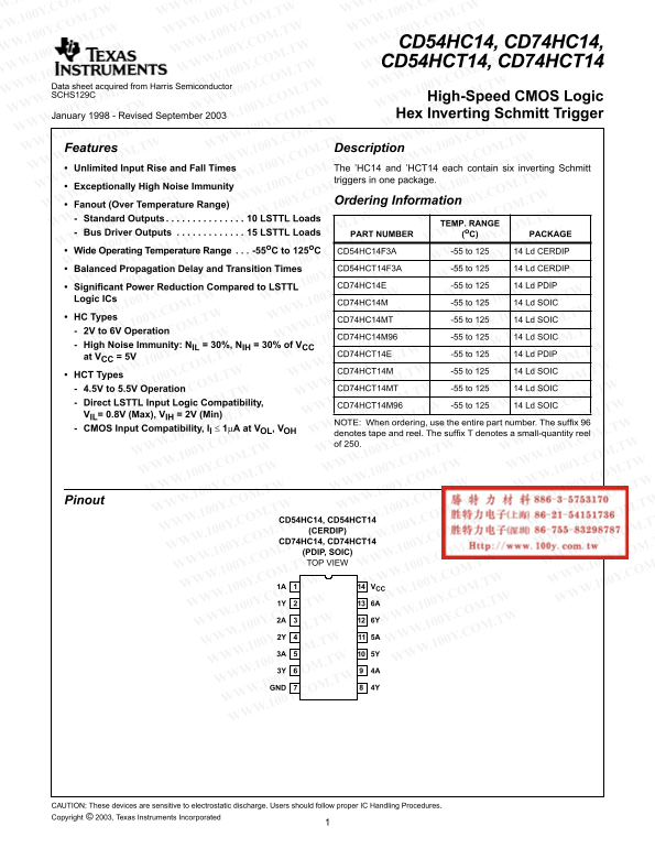
Page 1 Text Content
CD54HC14, CD74HC14, CD54HCT14, CD74HCT14
Data sheet acquired from Harris Semiconductor SCHS129C High-Speed CMOS Logic
January 1998 - Revised September 2003 Hex Inverting Schmitt Trigger
Features Description Unlimited Input Rise and Fall Times The ’HC14 and ’HCT14 each contain six inverting Schmitt
triggers in one package.
[ /Title Exceptionally High Noise Immunity
(CD74H Ordering Information
Fanout (Over Temperature Range) C14, Standard Outputs . . . . . . . . . . . . . . . 10 LSTTL Loads
TEMP. RANGE
CD74H Bus Driver Outputs . . . . . . . . . . . . . 15 LSTTL Loads PART NUMBER (o C) PACKAGE
CT14) Wide Operating Temperature Range . . . -55o C to 125o C
CD54HC14F3A -55 to 125 14 Ld CERDIP
/Subject
Balanced Propagation Delay and Transition Times CD54HCT14F3A -55 to 125 14 Ld CERDIP
(High
Significant Power Reduction Compared to LSTTL CD74HC14E -55 to 125 14 Ld PDIP
Speed
Logic ICs
CD74HC14M -55 to 125 14 Ld SOIC
HC Types
CD74HC14MT -55 to 125 14 Ld SOIC
Logic
2V to 6V Operation
Hex CD74HC14M96 -55 to 125 14 Ld SOIC
High Noise Immunity: NIL = 30%, NIH = 30% of VCC
Invert- CD74HCT14E -55 to 125 14 Ld PDIP
at VCC = 5V
CD74HCT14M -55 to 125 14 Ld SOIC
HCT Types
4.5V to 5.5V Operation CD74HCT14MT -55 to 125 14 Ld SOIC
Direct LSTTL Input Logic Compatibility,
CD74HCT14M96 -55 to 125 14 Ld SOIC
VIL= 0.8V (Max), VIH = 2V (Min)
NOTE: When ordering, use the entire part number. The suffix
CMOS Input Compatibility, Il 1µA at VOL, VOH
denotes tape and reel. The suffix denotes small-quantity reel of 250.
Pinout
CD54HC14, CD54HCT14 (CERDIP) CD74HC14, CD74HCT14 (PDIP, SOIC) TOP VIEW
1A VCC
GND 4Y
CAUTION: These devices are sensitive to electrostatic discharge. Users should follow proper IC Handling Procedures. Copyright © 2003, Texas Instruments Incorporated
Page Summary Contents For Texas Instruments CD54HC14, CD74HC14, CD54HCT14, CD74HCT14 Specifications and User Manual
Manual Details
| Brand | Texas Instruments |
|---|---|
| Pages | 8 |
| File Size | 160.34 KB |
| Published | June 18, 2026 |
Enter the captcha to get the download link:

Frequently Asked Questions
What is the required supply voltage range for these ICs?
HC types operate across a 2V to 6V range, while HCT types require 4.5V to 5.5V.
Is there a stable operating temperature range?
Yes, the devices maintain operation in a wide thermal range from -55°C to 125°C.
Are these components resistant to static electricity?
No, users must follow proper IC Handling Procedures because these devices are sensitive to electrostatic discharge.
Can I operate the device outside of listed ratings?
Operating above 'Absolute Maximum Ratings' is not implied and may cause permanent damage to the device.