Texas Instruments bq2031 Data Sheet User Guide
Summary
This manual describes the bq2031 Lead-Acid Fast-Charge IC, a versatile power management device optimized for lead-acid battery charging. It features pin-selectable charge algorithms, including constant-voltage and pulsed current modes, with built-in safety protections against overvoltage, temperature extremes, and damaged cells. Ideal for manufacturers requiring high-efficiency charging solutions, it offers temperature compensation and LED status monitoring.
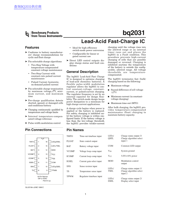
Page 1 Text Content
查询BQ2031供应商
bq2031
Lead-Acid Fast-Charge IC
Features charging until the voltage rises into
Ideal for high-efficiency
the allowed range or an internal
switch-mode power conversion
Conforms to battery manufactur- timer runs out and places the
Configurable for linear or
ers' charge recommendations for bq2031 in Fault condition. This
gated current use
cyclic and float charge procedure prevents high-current charging of cells that are possibly
Direct LED control outputs dis-
Pin-selectable charge algorithms
damaged or reversed. Charging is
play charge status and fault con-
Two-Step Voltage with inhibited anytime the temperature
ditions
temperature-compensated of the battery is outside the config- constant-voltage maintenance urable, allowed range. All voltage
General Description thresholds are temperature-
Two-Step Current with
compensated.
constant-rate pulsed current The bq2031 Lead-Acid Fast Charge maintenance IC is designed to optimize charging The bq2031 terminates fast (bulk)
of lead-acid chemistry batteries. charging based on the following:
Pulsed Current: hysteretic,
on-demand pulsed current flexible pulse-width modulation
Maximum voltage
regulator allows the bq2031 to con-
Pin-selectable charge termination trol constant-voltage, constant-
Second difference of cell voltage
by maximum voltage,∆2V, mini- current, or pulsed-current charging.
mum current, and maximum The regulator frequency is set by an time external capacitor for design flexi- Minimum current (in constant-
bility. The switch-mode design keeps voltage charging)
Pre-charge qualification detects
power dissipation to minimum for
shorted, opened, or damaged cells Maximum time-out (MTO)
high charge current applications.
and conditions battery
After bulk charging, the bq2031 pro-
charge cycle begins when power is
Charging continuously qualified by vides temperature-compensated
applied or the battery is replaced.
temperature and voltage limits maintenance (float) charging to
For safety, charging is inhibited un-
maintain battery capacity.
Internal temperature-compen- til the battery voltage is within con- sated voltage reference figured limits. If the battery voltage is less than the low-voltage threshold,
Pulse-width modulation control the bq2031 provides trickle-current
Pin Connections Pin Names
TMTO Time-out timebase input LED3/ Charge status output 3/ QSEL Charge algorithm select
FLOAT State control output input 1
TMTO LED2/DSEL
FLOAT LED1/TSEL BAT Battery voltage input COM Common LED output
BAT MOD
VCOMP Voltage loop comp input VSS System ground
VCOMP VCC
ICOMP Current loop comp input VCC 5.0V±10% power
ICOMP VSS
IGSEL Current gain select input MOD Modulation control
IGSEL COM
output
SNS LED3/QSEL SNS Sense resistor input
LED1/ Charge status output 1/
TS TPWM
TS Temperature sense input TSEL Charge algorithm select
input 2
16-Pin Narrow TPWM Regulator timebase input
DIP or SOIC LED2/ Charge status output 2/ PN203101.eps DSEL Display select input
SLUS156–JUNE 1999 E
Page Summary Contents For Texas Instruments bq2031 Data Sheet User Guide
Manual Details
| Brand | Texas Instruments |
|---|---|
| Pages | 16 |
| File Size | 154.76 KB |
| Published | June 15, 2026 |
Enter the captcha to get the download link:

Frequently Asked Questions
How does the bq2031 terminate fast charging?
Fast charging terminates based on maximum voltage, second difference of cell voltage (ΔV), minimum current (in constant-voltage charging), or maximum time-out (MTO).
What safety feature prevents charging of damaged batteries?
The bq2031 performs pre-charge qualification to detect shorted, opened, or damaged cells. Charging is inhibited if battery voltage is outside configured limits or temperature is outside the allowed range.
What charge algorithms does the bq2031 support?
Pin-selectable algorithms: Two-Step Voltage with temperature-compensated constant-voltage maintenance, Two-Step Current with constant-rate pulsed current maintenance, and Pulsed Current hysteretic on-demand pulsed current.
What is the function of the TMTO pin?
The TMTO (Time-out timebase input) sets the maximum charge time using an external resistor and capacitor determined by equation 6.