ST ANT2-20mm x 40mm M24LR16E-RO R Dual Interface EEPROM Antenna Reference Board
Summary
This specialized reference board simplifies the prototyping of Near Field Communication (NFC) applications. It consolidates a ready-to-use PCB featuring a 13.56 MHz antenna and an M24LR16E-R Dual Interface EEPROM IC. Designed for system engineers, this module allows comprehensive evaluation of NFC systems using energy harvesting capabilities. The manual provides full documentation, including setup guides, required associated PC software, and technical details to help designers integrate robust, reliable NFC functionality into their next product development.
Page 1 Text Content
ANT2-M24LR16E
20 mm x 40 mm antenna reference board for the M24LR16E-R Dual Interface EEPROM
Data brief
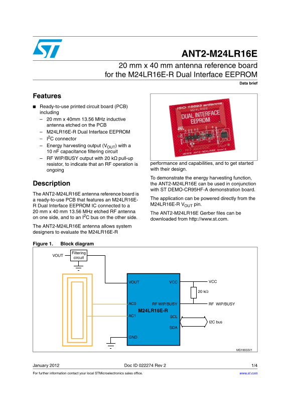
Features Ready-to-use printed circuit board (PCB) including 20 mm x 40mm 13.56 MHz inductive antenna etched on the PCB M24LR16E-R Dual Interface EEPROM I2C connector Energy harvesting output (VOUT) with a
n F capacitance filtering circuit RF WIP/BUSY output with 20 kΩ pull-up
resistor, to indicate that an RF operation is performance and capabilities, and to get started ongoing with their design. To demonstrate the energy harvesting function, Description the ANT2-M24LR16E can be used in conjunction with ST DEMO-CR95HF-A demonstration board.
The ANT2-M24LR16E antenna reference board is
The application can be powered directly from the
a ready-to-use PCB that features an M24LR16E-
M24LR16E-R VOUT pin.
R Dual Interface EEPROM IC connected to a mm x 40 mm 13.56 MHz etched RF antenna
The ANT2-M24LR16E Gerber files can be
on one side, and to an I2C bus on the other side.
downloaded from http://www.st.com.
The ANT2-M24LR16E antenna allows system designers to evaluate the M24LR16E-R
Figure 1. Block diagram
January 2012 Doc ID 022274 Rev 2 1/4 For further information contact your local STMicroelectronics sales office. www.st.com
Page Summary Contents For ST ANT2-20mm x 40mm M24LR16E-RO R Dual Interface EEPROM Antenna Reference Board
Manual Details
| Brand | Dual |
|---|---|
| Pages | 4 |
| File Size | 138.52 KB |
| Published | June 05, 2026 |
Enter the captcha to get the download link:

Frequently Asked Questions
How can I control the energy harvesting function?
Use the Dual Interface EEPROM tool software available from http://www.st.com.
What type of components are included on the board?
It includes a 13.56 MHz inductive antenna, an M24LR16E-R Dual Interface EEPROM IC, and an energy harvesting output circuit.
Can I download custom layout files for this PCB?
Yes, the ANT2-M24LR16E Gerber files are available for download from http://www.st.com.
What operational cautions apply to ST products?
ST Products should not be used in military, air craft, space, life saving, or life sustaining applications unless explicitly authorized.