ST ANT7-024LR16E 15 mm x 15 mm double layer antenna reference board for the M24LR16E-3 Dual Interface EEPROM User Manual
Summary
The ANT7-M24LR16E is a professional reference board designed for system engineers and designers evaluating the M24LR16E-R Dual Interface EEPROM. This ready-to-use PCB demonstrates core capabilities, including NFC energy harvesting and reliable dual-interface communication using an etched 13.56 MHz antenna. The accompanying manual provides comprehensive resources, including design files, detailed block diagrams, and dedicated PC software to fully configure, control, and optimize the embedded functions for your next wireless project.
Page 1 Text Content
ANT7-M24LR16E
15 mm x 15 mm double layer antenna reference board for the M24LR16E-R Dual Interface EEPROM
Data brief
Features Ready-to-use printed circuit board (PCB) including 15 mm x 15 mm 13.56 MHz inductive antenna etched on the PCB M24LR16E-R Dual Interface EEPROM I2C connector Energy harvesting output (VOUT) with a
n F capacitance filtering circuit RF WIP/BUSY output with 20 kΩ pull-up resistor, to indicate that an RF operation is
The ANT7-M24LR16E antenna allows system
ongoing
designers to evaluate the M24LR16E-R performance and capabilities, and to get started Description with their design. To demonstrate the energy harvesting function,
The ANT7-M24LR16E antenna reference board is
the ANT7-M24LR16E can be used in conjunction
a ready-to-use PCB that features an M24LR16E-
with ST DEMO-CR95HF-A demonstration board.
R Dual Interface EEPROM IC connected to a mm x 15 mm 13.56 MHz etched RF double
The application can be powered directly from the
layer antenna on one side, and to an I2C bus on
M24LR16E-R VOUT pin.
the other side.
The ANT7-M24LR16E Gerber files can be downloaded from http://www.st.com.
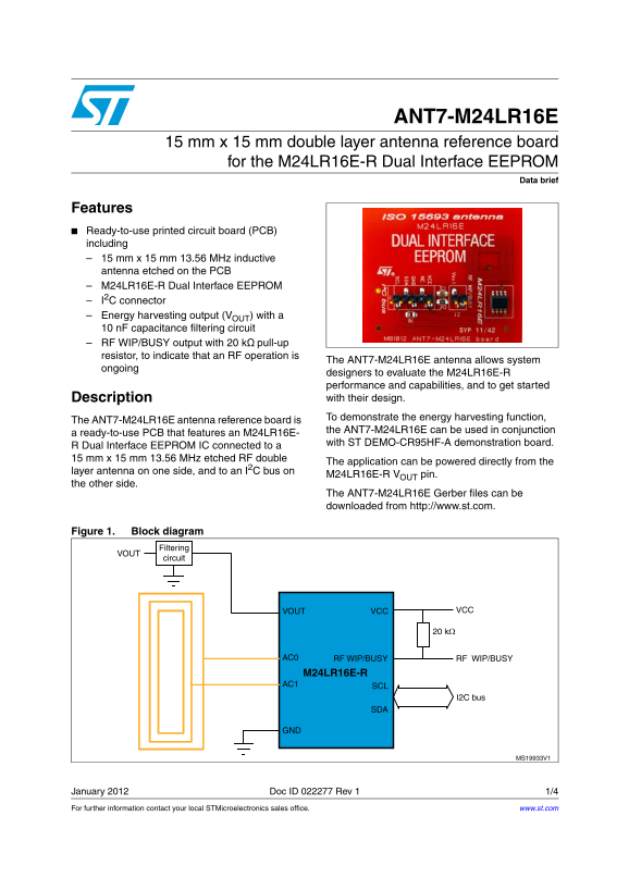
Figure 1. Block diagram
January 2012 Doc ID 022277 Rev 1 1/4 For further information contact your local STMicroelectronics sales office. www.st.com
Page Summary Contents For ST ANT7-024LR16E 15 mm x 15 mm double layer antenna reference board for the M24LR16E-3 Dual Interface EEPROM User Manual
Manual Details
| Brand | Dual |
|---|---|
| Pages | 4 |
| File Size | 134.90 KB |
| Published | June 05, 2026 |
Enter the captcha to get the download link:

Frequently Asked Questions
What is the working frequency of the antenna board?
The board features a 15 mm x 15 mm inductive antenna etched at 13.56 MHz.
How do I control or configure the energy harvesting function?
You must use the supported PC software, the Dual Interface EEPROM tool, available from http://www.st.com.
What are the connection points for power and data on the board?
The application can be powered directly from the antenna side while connecting the IC bus on the other side.
Is there an indicator to show if an RF operation is active?
Yes, the RF WIP/BUSY output includes a 20 kΩ pull-up resistor specifically for this indication.