# A B C D E F G H I J K L M N O P Q R S T U V W X Y Z

Siemens TDA 4601 Data Manual

Summary

Optimized for stable performance in self-oscillating flyback converter power supplies, this integrated circuit precisely drives, controls, and protects switching transistors. The TDA 4601 ensures reliable operation during startup, normal loads, and severe disturbances by preventing secondary voltage spikes. This documentation provides detailed technical instruction on the chip's proprietary control logic and operating modes. Essential for engineers developing high-stability power solutions for consumer electronics—including TV sets, audio equipment, and sophisticated professional industrial units.
📄 Preview PAGE OF 26

Page 1 Text Content

查询TDA 4601供应商

Control ICs for Switched-Mode Power Supplies TDA 4601

Bipolar IC

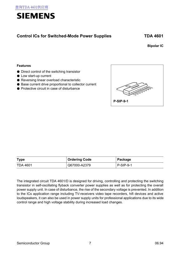
Features Direct control of the switching transistor Low start-up current Reversing linear overload characteristic Base current drive proportional to collector current Protective circuit in case of disturbance

P-SIP-9-1

Type Ordering Code Package TDA 4601 Q67000-A2379 P-SIP-9-1

The integrated circuit TDA 4601/D is designed for driving, controlling and protecting the switching transistor in self-oscillating flyback converter power supplies as well as for protecting the overall power supply unit. In case of disturbance, the rise of the secondary voltage is prevented. In addition to the ICs application range including TV-receivers video tape recorders, hifi devices and active loudspeakers, it can also be used in power supply units for professional applications due to its wide control range and high voltage stability during increased load changes.

Semiconductor Group 06.94

Page Summary Contents For Siemens TDA 4601 Data Manual

Page 1 查询TDA 4601供应商 Control ICs for Switched-Mode Power Supplies TDA 4601 Bipolar IC Features Direct control of the switching transistor Low start-up current Reversing linear overload characteristic Base cu...
Page 2 TDA 4601 Pin Definitions and Functions Pin No. Function VREF output Zero passage identification Input control amplifier, overload amplifier Collector current simulation Connection for additional prote...
Page 3 TDA 4601 Circuit Description The TDA 4601 is designed for driving, controlling and protecting the switching transistor in flyback converter power supplies during start-up, normal and overload operatio...
Page 4 TDA 4601 The output levels of the control amplifier as well as those of the overload identification and collector current simulator are compared in the trigger and forwarded to the control logic. Via ...
Page 5 TDA 4601 In case of continuing problems of disturbance (V5 V1/2 0.1 V) the switch-on mode is interrupted by the periodic protective operating mode described above, i.e. pin 8 is inhibited and V9 is fa...
Page 6 TDA 4601 Absolute Maximum Ratings Parameter Symbol Limit Values Unit min. max. Supply voltage V9 Voltages Reference output V1 Zero passage identification V2 – 0.6 0.6 Control amplifier V3 Collector cu...
Page 7 TDA 4601 Absolute Maximum Ratings (cont’d) Parameter Symbol Limit Values Unit min. max. Operating Range Supply voltage V9 7.8 Case temperature TDA 4601 TC ˚C Ambient temperature range TDA 4601-D TA ˚C...
Page 8 TDA 4601 Characteristics TA = 25 ˚C according to measurement circuit 1 and diagram Parameter Symbol Limit Values Unit min. typ. max. Start Operation Current consumption (V1 not yet switched on) V9 = 2...
Page 9 TDA 4601 Protective Operation V9 = 10 V; Vcont = – 10 V; Vclock = ± 0.5 V; f = 20 k Hz; duty cycle 1:2 Parameter Symbol Limit Values Unit min. typ. max. Current consumption V5 < 1.9 V I9 m A Switch...
Page 10 TDA 4601 Circuit Diagram Semiconductor Group
Page 11 TDA 4601 Test and Measurement Circuit 1 Test Diagram: Overload Operation Semiconductor Group
Page 12 TDA 4601 Wide range from 80 to 270 Vac Application Circuit 2 Semiconductor Group
Page 13 TDA 4601 Notes on Application Circuit 2 Wide Range SMPS Filtering of the rectified AC-voltage has been increased up to 470 µF to ensure a constant and hum- free supply at Vline Vac. The stabilized pha...
Page 14 TDA 4601 Supplements to Application Circuit 2 Efficiency versus Output Power Efficiency versus Output Power Semiconductor Group
Page 15 TDA 4601 Supplements to Application Circuit 2 Load Characteristics V2sec = f (I2sec) Output Voltage V2sec (line change) Semiconductor Group
Page 16 TDA 4601 Further Applications Application Circuit 3 Semiconductor Group
Page 17 TDA 4601 Notes on Application Circuit 3 Fully Insulated, Clamp-contacted PTC-Thermistor Suitable for SMPS-Applications at Increased Start-Up Currents The newly developed PTC-thermistor Q63100-P2462-J2...
Page 18 TDA 4601 Application Circuit 4 Semiconductor Group
Page 19 TDA 4601 Notes on Application Circuit 4 Improved Load Control and Short-Circuit Characteristics Turn-on is the same as for circuit 3. To make the price more attractive, switching transistor BU 508 A w...
Page 20 TDA 4601 Application Circuit 5 Semiconductor Group
Page 21 TDA 4601 Notes on Application Circuit 5 Highly Stable Secondary Side Power supplies for commercial purposes require highly constant low voltages and high currents which, on the basis of the flyback co...
Page 22 TDA 4601 Application Circuit 6 Semiconductor Group
Page 23 TDA 4601 Notes on Application Circuit 6 Wide Range Plug SMPS up to 30 W Due to their volume and weight, plug SMPS have so far been limited to a restricted primary voltage and a secondary power of no m...
Page 24 TDA 4601 Application Circuit 7 Semiconductor Group
Page 25 TDA 4601 Notes on Application Circuit 7 Wide Range SMPS with Reducing Peak Collector Current IC BU 208 for Rising Line Voltage (variable point of return) Wide range SMPS have to be dimensioned at line...
Page 26 TDA 4601 Load Characteristics Figure 1 Figure 2 Semiconductor Group

Manual Details

Brand Siemens
Pages 26
File Size 1.32 MB
Published June 05, 2026
57 views

Enter the captcha to get the download link:

captcha

Frequently Asked Questions

What types of devices are compatible with this IC?

It can be used in TV-receivers, VCRs, hifi devices and active loudspeakers, or professional power supply units.

How does the TDA 4601 initiate operation?

Start-up involves three phases: building internal reference voltage, enabling a key internal voltage (approx. 12V), and finally activating the control logic.

What safety features are included in the design?

The IC protects against disturbances by inhibiting the switching transistor drive and preventing any rise of secondary voltage.