Siemens BFT 92W Data Sheet / Manual
Summary
Optimize your RF amplifier design with this high-performance silicon transistor. Rated for broadband amplification up to 2GHz and handling collector currents of up to 20mA, it offers reliable performance in demanding electronic applications. This comprehensive manual details the core operating parameters, including transition frequency curves, power gain (S21) versus frequency and current, breakdown voltages, and capacitance values. It is an essential reference guide for RF circuit designers and engineers who require precise selection and implementation of high-frequency switching components.
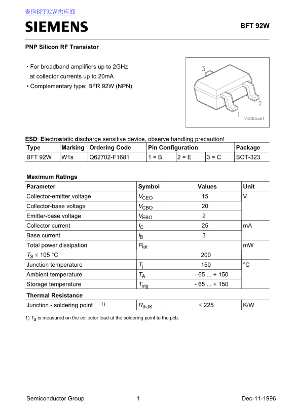
Page 1 Text Content
查询BFT92W供应商
BFT 92W
PNP Silicon RF Transistor
• For broadband amplifiers up to 2GHz at collector currents up to 20m A • Complementary type: BFR 92W (NPN)
ESD: Electrostatic discharge sensitive device, observe handling precaution! Type Marking Ordering Code Pin Configuration Package BFT 92W W1s Q62702-F1681 1 = B 2 = E 3 = C SOT-323
Maximum Ratings Parameter Symbol Values Unit Collector-emitter voltage VCEO Collector-base voltage VCBO Emitter-base voltage VEBO Collector current IC m A Base current IB Total power dissipation Ptot m W TS ≤ 105 °C Junction temperature Tj °C Ambient temperature TA - 65 ... + 150 Storage temperature Tstg - 65 ... + 150 Thermal Resistance Junction - soldering point 1) Rth JS ≤ 225 K/W
1) TS is measured on the collector lead at the soldering point to the pcb.
Semiconductor Group Dec-11-1996
Page Summary Contents For Siemens BFT 92W Data Sheet / Manual
Manual Details
| Brand | Siemens |
|---|---|
| Pages | 7 |
| File Size | 59.20 KB |
| Published | June 04, 2026 |
Enter the captcha to get the download link:

Frequently Asked Questions
What is the maximum allowed junction temperature?
The maximum total power dissipation allows continuous operation up to a junction temperature (Tj) of 150°C.
Are there any handling precautions for this device?
Yes, as it is an ESD sensitive device, observe handling precaution when using BFT 92W.
What are the performance specifications for its gain?
The power gain (G) ranges from 5 to 16 dB across frequencies depending on operating voltage and current.
What type of tests determine allowable pulse loading?
Allowable pulse loading is assessed using time domain data derived from parameters like 'D' (Pulse Load) in relation to junction temperature.