ROHM TT8M2 Data Sheet
Summary
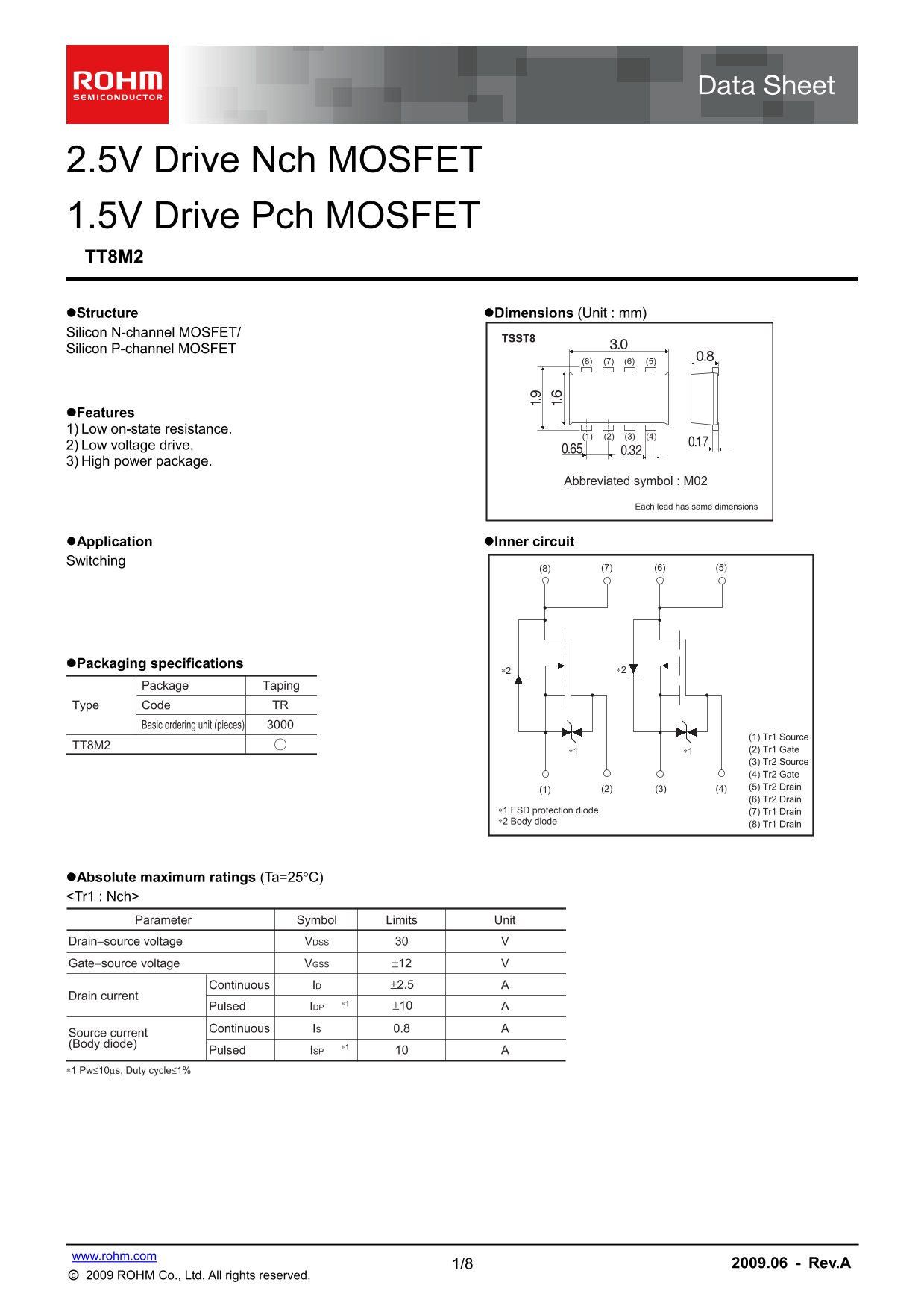
This high-power MOSFET module integrates both N-channel and P-channel components in a durable TT8M2 package, optimized for reliable electronic switching applications. Featuring low on-state resistance and low voltage drive capabilities, this component is ideal for general-use equipment like audio/visual, communication devices, and automated appliances. The accompanying manual provides comprehensive details on absolute maximum ratings, detailed electrical characteristics, packaging specifications, and critical timing parameters to ensure optimal circuit design.
Page 1 Text Content
2.5V Drive Nch MOSFET 1.5V Drive Pch MOSFET TT8M2 Structure Dimensions (Unit : mm) Silicon N-channel MOSFET/
TSST8
Silicon P-channel MOSFET
Features 1) Low on-state resistance.
2) Low voltage drive. 3) High power package.
Abbreviated symbol : M02
Each lead has same dimensions
Application Inner circuit Switching
Packaging specifications
Package Taping
Type Code TR
Basic ordering unit (pieces)
(1) Tr1 Source
TT8M2
∗1 ∗1 (2) Tr1 Gate (3) Tr2 Source (4) Tr2 Gate (1) (4)(3)(2) (5) Tr2 Drain (6) Tr2 Drain
∗1 ESD protection diode (7) Tr1 Drain ∗2 Body diode (8) Tr1 Drain
Absolute maximum ratings (Ta=25°C) <Tr1 : Nch>
Parameter Symbol Limits Unit
Drain−source voltage VDSS
Gate−source voltage VGSS ±12
Continuous ID ±2.5
Drain current
Pulsed IDP ±10
Continuous IS 0.8
Source current (Body diode) ∗1
Pulsed ISP
∗1 Pw≤10µs, Duty cycle≤1%
1/8 www.rohm.com 2009.06 - Rev.A
○c 2009 ROHM Co., Ltd. All rights reserved.
Page Summary Contents For ROHM TT8M2 Data Sheet
Manual Details
| Brand | ROHM |
|---|---|
| Pages | 9 |
| File Size | 261.71 KB |
| Published | July 15, 2026 |
Enter the captcha to get the download link:

Frequently Asked Questions
What is the maximum total power dissipation?
The maximum specified value for Total power dissipation (PD) is 1.25 W.
Can this device be used in safety-critical equipment like medical instruments?
No, it should not be used in equipment that requires an extremely high level of reliability or poses a direct threat to human life.
What are the operating voltage ranges for the MOSFETs?
The N-channel (Tr1) accepts up to ±12 V for Gate-source voltage (VGSS).
How should I handle exporting this product internationally?
You may be required to obtain a license or permit under the Foreign Exchange and the Foreign Trade Law.