ROHM 2SAR543R Data Sheet
Summary
This medium-power PNP Silicon epitaxial planar transistor is designed for high-reliability, high-speed switching applications requiring low saturation voltage $\text{V}_{CE(sat)}$. The associated technical manual serves as a comprehensive resource for electronics engineers and product designers. It details absolute maximum ratings, critical electrical characteristics (including current gain $h$ and transition frequency $f_T$), and detailed operating curves, enabling accurate integration into demanding medium-power circuits and electronic control systems.
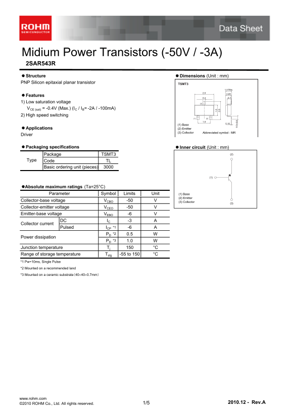
Page 1 Text Content
Midium Power Transistors (-50V / -3A) 2SAR543R Structure Dimensions (Unit : mm) PNP Silicon epitaxial planar transistor
TSMT3
Features 1) Low saturation voltage
VCE (sat) = -0.4V (Max.) (IC / IB= -2A / -100m A) 2) High speed switching
(1) Base
Applications (2) Emitter
(3) Collector Abbreviated symbol : MR
Driver
Packaging specifications Inner circuit (Unit : mm)
Package TSMT3 (2)
Type Code TL Basic ordering unit (pieces)
Absolute maximum ratings (Ta=25°C)
Parameter Symbol Limits Unit (1) Base
(2) Emitter
Collector-base voltage VCBO -50
(3) Collector
Collector-emitter voltage VCEO -50 Emitter-base voltage VEBO -6
DC IC -3
Collector current
Pulsed ICP *1 -6 PD *2 0.5
Power dissipation
PD *3 1.0
Junction temperature Tj °C
Range of storage temperature Tstg -55 to 150 °C *1 Pw=10ms, Single Pulse *2 Mounted on a recommended land *3 Mounted on a ceramic substrate(40400.7mm)
www.rohm.com
©2010 ROHM Co., Ltd. All rights reserved. 1/5 2010.12 - Rev.A
Page Summary Contents For ROHM 2SAR543R Data Sheet
Manual Details
| Brand | ROHM |
|---|---|
| Pages | 6 |
| File Size | 489.42 KB |
| Published | June 01, 2026 |
Enter the captcha to get the download link:

Frequently Asked Questions
What applications are restricted for this transistor?
It should not be used in equipment requiring an extremely high level of reliability, such as medical, aerospace, or nuclear control devices.
What is the maximum absolute voltage and current rating?
The ratings are a Collector-base voltage (Vcb) of -50V and a Collector-emitter voltage (Vce) of -50V, with a DC collector current limit of -3A.
How should I mount this transistor for safe operation?
It must be mounted on either a recommended land or a ceramic substrate to properly dissipate heat.
What is the typical Collector-emitter saturation voltage (Vce(sat))?
The typical range for Vce(sat) when operating at I = -2A and II = -100mA is between -200mV and -400mV.