ROHM RT1A050ZP Specification Sheet and User Guide
Summary
A high-performance P-channel MOSFET designed for efficient power switching applications. This component features exceptionally low on-resistance and accepts low voltage drive, ensuring reliable performance in various electronic devices. The comprehensive manual details absolute maximum ratings, junction temperature limits, thermal characteristics, complex electrical parameters (including switching delays and body diode specs), providing engineers with all necessary data for optimal circuit design and integration into demanding circuits.
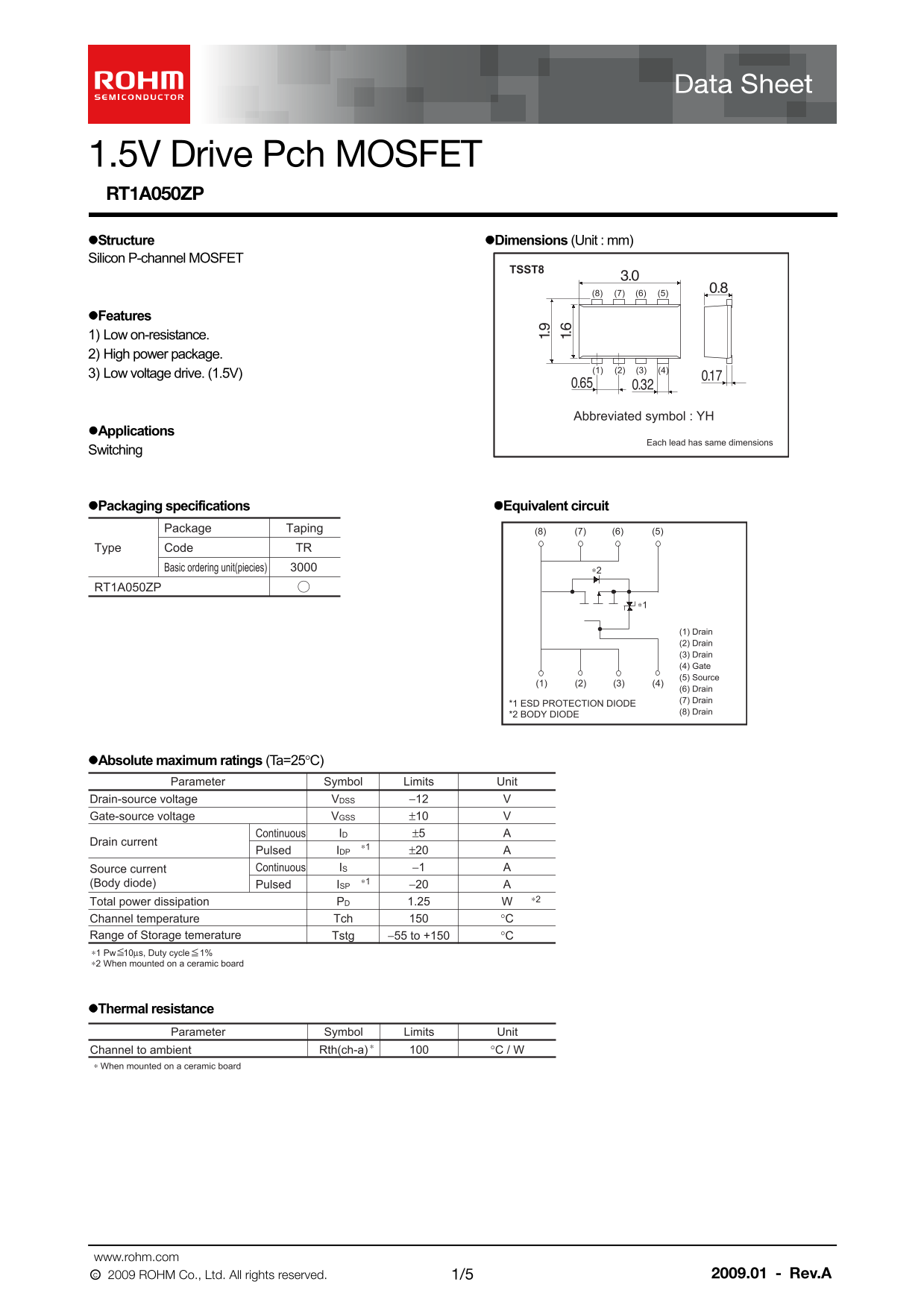
Page 1 Text Content
1.5V Drive Pch MOSFET RT1A050ZP Structure Dimensions (Unit : mm) Silicon P-channel MOSFET
TSST8
Features 1) Low on-resistance. 2) High power package.
3) Low voltage drive. (1.5V)
Abbreviated symbol : YH
Applications
Each lead has same dimensions
Switching
Packaging specifications Equivalent circuit
Package Taping (8) (7) (6) (5)
Type Code TR
Basic ordering unit(piecies) ∗2
RT1A050ZP
(1) Drain (2) Drain (3) Drain (4) Gate (5) Source
(6) Drain (7) Drain
*1 ESD PROTECTION DIODE
*2 BODY DIODE (8) Drain
Absolute maximum ratings (Ta=25°C)
Parameter Symbol Limits Unit
Drain-source voltage −12 VVDSS
Gate-source voltage ±10 VVGSS
Continuous ±5 AID
Drain current
Pulsed ±20 AIDP
Source current Continuous −1 AIS
(Body diode) ∗1
Pulsed −20 AISP
1.25 WPD ∗2
Total power dissipation
Channel temperature °CTch
Range of Storage temerature −55 to +150 °CTstg ∗1 Pw 10µs, Duty cycle 1% ∗2 When mounted on a ceramic board
Thermal resistance
Parameter Symbol Limits Unit
Channel to ambient °C / WRth(ch-a)
∗ When mounted on a ceramic board
www.rohm.com
○c 2009 ROHM Co., Ltd. All rights reserved. 2009.01 - 1/5 Rev.A
Page Summary Contents For ROHM RT1A050ZP Specification Sheet and User Guide
Manual Details
| Brand | ROHM |
|---|---|
| Pages | 6 |
| File Size | 214.73 KB |
| Published | June 22, 2026 |
Enter the captcha to get the download link:

Frequently Asked Questions
What is the low voltage driving requirement?
The MOSFET requires a low voltage drive of 1.5V.
What is the peak power dissipation limit?
The maximum total power dissipation (P_D) for this device is 1.25 W.
What are the typical body diode characteristics?
When operating in continuous mode, the body diode has a typical forward voltage (VSD) of -1.2 V at -5A.
What are the typical on-state resistance ranges?
The static drain-source on-state resistance (RDS(on)) varies depending on current and gate-source voltage, with values like 26–36 mΩ or 34–50 mΩ.