ROHM EMX4 UMX4N IMX4 Data Handbook/Specification Sheet
Summary
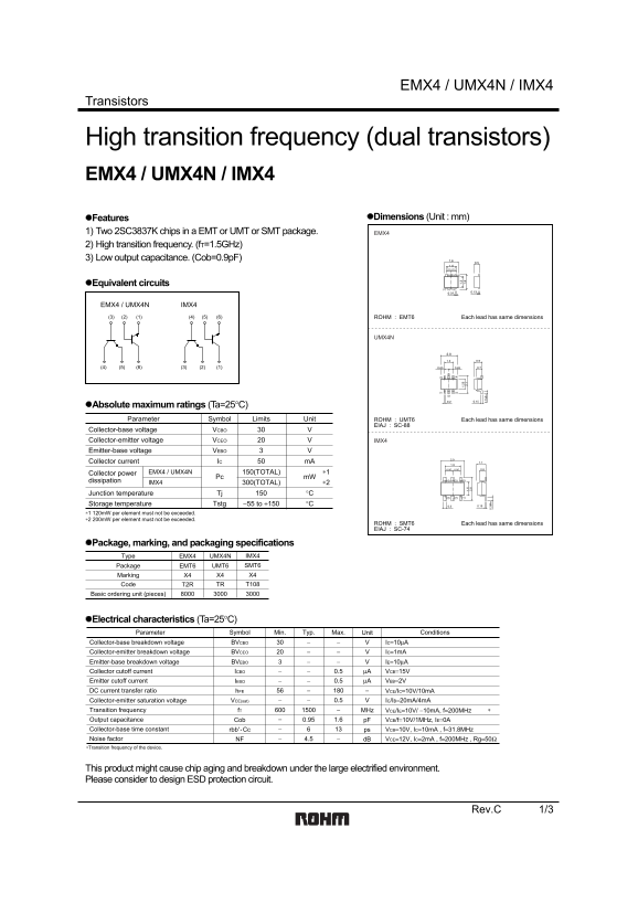
Dual high-frequency transistors featuring a transition frequency of 1.5GHz, low output capacitance, and a total collector current of 150mA. Ideal for high-speed switching and RF applications.
Page 1 Text Content
EMX4 / UMX4N / IMX4
Transistors
High transition frequency (dual transistors) EMX4 / UMX4N / IMX4
Features Dimensions (Unit : mm)
1) Two 2SC3837K chips in a EMT or UMT or SMT package. EMX4 2) High transition frequency. (f T=1.5GHz) 3) Low output capacitance. (Cob=0.9p F)
Equivalent circuits
EMX4 / UMX4N IMX4 (3) (2) (1) (4) (5) (6) Each lead has same dimensions ROHM : EMT6
UMX4N
Absolute maximum ratings (Ta=25°C)
Parameter Symbol Limits Unit Each lead has same dimensions ROHM : UMT6
EIAJ : SC-88
Collector-base voltage VCBO Collector-emitter voltage VCEO IMX4 Emitter-base voltage VEBO Collector current IC m A
Collector power 150(TOTAL)EMX4 / UMX4N ∗1
Pc m W
dissipation IMX4 300(TOTAL) ∗2
Junction temperature Tj °C Storage temperature Tstg −55 to +150 °C
∗1 120m W per element must not be exceeded. ∗2 200m W per element must not be exceeded.
Each lead has same dimensions ROHM : SMT6
EIAJ : SC-74
Package, marking, and packaging specifications
Type EMX4 UMX4N IMX4 Package EMT6 UMT6 SMT6 Marking X4 X4 X4 Code T2R TR T108
Basic ordering unit (pieces)
Electrical characteristics (Ta=25°C)
Parameter Symbol Min. Typ. Max. Unit Conditions
Collector-base breakdown voltage BVCBO IC=10µA
Collector-emitter breakdown voltage BVCEO IC=1m A Emitter-base breakdown voltage BVEBO IE=10µA Collector cutoff current ICBO 0.5 µA VCB=15V
Emitter cutoff current IEBO 0.5 µA VEB=2V DC current transfer ratio h FE VCE/IC=10V/10m A
Collector-emitter saturation voltage VCE(sat) 0.5 IC/IB=20m A/4m A
Transition frequency f T MHz VCE/IE=10V/ −10m A, f=200MHz Output capacitance Cob 0.95 1.6 p F VCB/f=10V/1MHz, IE=0A
13rbb' Cc ps VCB=10V, IC=10m A , f=31.8MHz Collector-base time constant 4.5 −NF d B VCE=12V, IC=2m A , f=200MHz , Rg=50ΩNoise factor
∗Transition frequency of the device.
This product might cause chip aging and breakdown under the large electrified environment. Please consider to design ESD protection circuit.
Rev.C 1/3
Page Summary Contents For ROHM EMX4 UMX4N IMX4 Data Handbook/Specification Sheet
Manual Details
| Brand | ROHM |
|---|---|
| Pages | 4 |
| File Size | 107.73 KB |
| Published | June 15, 2026 |
Enter the captcha to get the download link:

Frequently Asked Questions
What are the maximum collector-base and collector-emitter voltages?
The absolute maximum collector-base voltage (VCBO) is 30V and collector-emitter voltage (VCEO) is 20V.
What packages and markings are available for the EMX4/UMX4N/IMX4 transistors?
They come in EMT6 (EMX4), UMT6 (UMX4N), or SMT6 (IMX4) packages, all marked with X4.
What is the typical transition frequency?
The typical transition frequency (fT) is 1500MHz (1.5GHz), with a minimum of 600MHz.
What safety design considerations are mentioned?
Consider designing an ESD protection circuit to prevent chip aging/breakdown in large electrified environments.