ROHM MNR34J5ABJ Specifications and User Guide
Summary
These compact chip resistor networks are designed for high-density mounting, allowing precise circuit design with reduced parts count and cost savings. The resistors feature convex electrodes compatible with a wide range of electronic mounting equipment, making them ideal for sophisticated image recognition applications. This manual provides comprehensive technical data, including detailed ratings for power derating, operating temperature ranges (-55°C to +125°C), and thorough guides on electrical testing and soldering conditions. This component is engineered for circuit board designers requiring reliable, robust resistive elements that maintain performance in demanding environments.
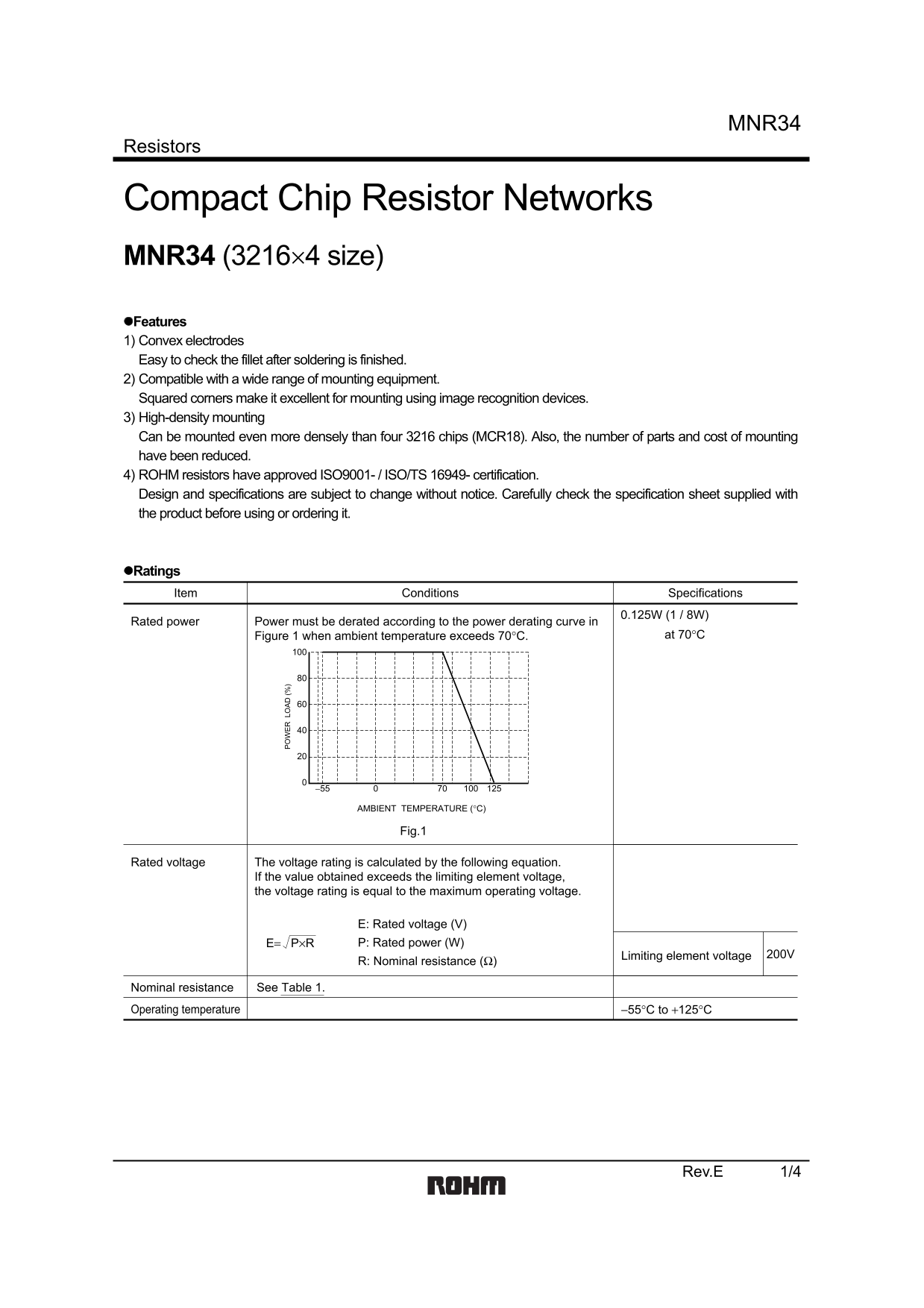
Page 1 Text Content
MNR34
Resistors
Compact Chip Resistor Networks MNR34 (3216×4 size) Features 1) Convex electrodes Easy to check the fillet after soldering is finished. 2) Compatible with a wide range of mounting equipment. Squared corners make it excellent for mounting using image recognition devices. 3) High-density mounting Can be mounted even more densely than four 3216 chips (MCR18). Also, the number of parts and cost of mounting have been reduced. 4) ROHM resistors have approved ISO9001- / ISO/TS 16949- certification. Design and specifications are subject to change without notice. Carefully check the specification sheet supplied with the product before using or ordering it.
Ratings Item Conditions Specifications
0.125W (1 / 8W)Rated power
Power must be derated according to the power derating curve in
Figure 1 when ambient temperature exceeds 70°C. at 70°C
AMBIENT TEMPERATURE (°C)
Fig.1
Rated voltage The voltage rating is calculated by the following equation. If the value obtained exceeds the limiting element voltage, the voltage rating is equal to the maximum operating voltage.
E: Rated voltage (V) E= P×R P: Rated power (W)
Limiting element voltage 200V
R: Nominal resistance (Ω)
Nominal resistance See Table 1.
Operating temperature −55°C to +125°C
Rev.E 1/4
Page Summary Contents For ROHM MNR34J5ABJ Specifications and User Guide
Manual Details
| Brand | ROHM |
|---|---|
| Pages | 5 |
| File Size | 83.80 KB |
| Published | June 22, 2026 |
Enter the captcha to get the download link:

Frequently Asked Questions
How can I ensure proper component reliability during operation?
The component should be evaluated in its mounted state, especially when exposed to transients like pulse loads, and must not operate above its rated voltage.
What is the recommended temperature for soldering this resistor network?
For standard soldering conditions, immerse the components in a bath at 235±5°C for a duration of 2.0±0.5s.
Does this product support high-density mounting?
Yes, it can be mounted even more densely than four 3216 chips (MCR18), which reduces the count and cost of parts and mounting equipment.
What condition must I meet if the ambient temperature exceeds 70°C?
If the ambient temperature exceeds 70°C, the rated power must be derated according to the power derating curve provided in Figure 1.