ROHM LTR50UZPJ Data Sheet
Summary
Discover high-performance thick film resistors designed for critical applications in automotive, industrial, and power supply systems. This comprehensive guide provides engineers with detailed specifications, operating curves, and rigorous reliability data, emphasizing superior welding strength and increased surge resistance. Review application guidelines, temperature derating graphs, and precise component details to ensure reliable circuit design and optimal performance integration.
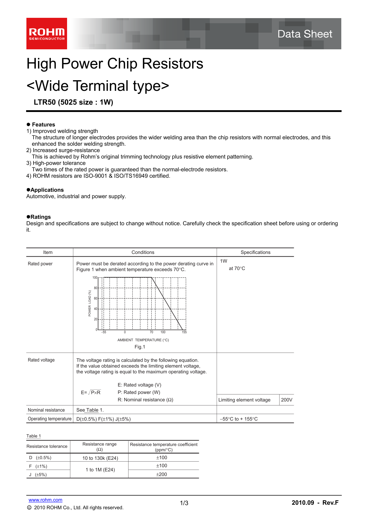
Page 1 Text Content
High Power Chip Resistors <Wide Terminal type> LTR50 (5025 size : 1W) Features 1) Improved welding strength The structure of longer electrodes provides the wider welding area than the chip resistors with normal electrodes, and this enhanced the solder welding strength. 2) Increased surge-resistance This is achieved by Rohm’s original trimming technology plus resistive element patterning. 3) High-power tolerance Two times of the rated power is guaranteed than the normal-electrode resistors. 4) ROHM resistors are ISO-9001 & ISO/TS16949 certified. Applications Automotive, industrial and power supply.
Ratings Design and specifications are subject to change without notice. Carefully check the specification sheet before using or ordering it.
Item Conditions Specifications
Rated power Power must be derated according to the power derating curve in
Figure 1 when ambient temperature exceeds 70°C. at 70°C
AMBIENT TEMPERATURE (°C)
Fig.1
Rated voltage The voltage rating is calculated by the following equation.
If the value obtained exceeds the limiting element voltage, the voltage rating is equal to the maximum operating voltage.
E: Rated voltage (V) E= P×R P: Rated power (W) R: Nominal resistance (Ω) Limiting element voltage 200V
Nominal resistance See Table 1.
Operating temperature D(±0.5%) F(±1%) J(±5%) −55°C to + 155°C
Table 1
Resistance range Resistance temperature coefficient
Resistance tolerance
(Ω) (ppm/°C)
D (±0.5%) 10 to 130k (E24) ±100
1 to 1M (E24)
www.rohm.com
1/3 2010.09 - Rev.F
○c 2010 ROHM Co., Ltd. All rights reserved.
Page Summary Contents For ROHM LTR50UZPJ Data Sheet
Manual Details
| Brand | ROHM |
|---|---|
| Pages | 4 |
| File Size | 135.44 KB |
| Published | July 16, 2026 |
Enter the captcha to get the download link:

Frequently Asked Questions
Is power derating required at high ambient temperatures?
Yes, if the ambient temperature exceeds 70°C, the rated power must be derated according to the specified curve.
How is the product's voltage rating determined?
The rated voltage (E) is calculated by dividing the product of rated power (P) and nominal resistance (R) by the limiting element voltage: E = P × R / Limiting element voltage.
What are the usage limitations concerning voltage?
Reliability cannot be guaranteed if the resistor is used with a steady state voltage that is greater than its specified rated voltage.
In what industrial fields are these resistors typically used?
They are commonly applied in automotive, industrial, and power supply circuits.