ROHM LTR18EZPF User Guide and Manual
Summary
Discover highly reliable LTR18 High Power Chip Resistors with wide terminals, engineered for critical applications in automotive, industrial, and power supply sectors. This manual provides comprehensive technical documentation, detailing enhanced welding strength (wider electrode area) and increased surge resistance capabilities. It includes full performance specifications, operating temperature ranges up to 155°C, structural dimensions, rigorous testing details (such as thermal endurance and vibration), and complete ordering guidelines to ensure proper component selection and integration in demanding circuits.
Page 1 Text Content
High Power Chip Resistors <Wide Terminal type> LTR18 (3216 size : 1 / 2W) Features 1) mproved welding strength The structure of longer electrodes provides the wider welding area than the chip resistors with normal electrodes, and this enhanced the solder welding strength. 2) Increased surge-resistance This is achieved by Rohm’s original trimming technology plus resistive element patterning. 3) High-power tolerance Two times of the rated power is guaranteed than the normal-electrode resistors. ROHM resistors are ISO-9001 & ISO/TS16949 certified.
Applications Automotive, industrial and power supply.
Ratings Design and specifications are subject to change without notice. Carefully check the specification sheet before using or ordering it. Item Conditions Specifications
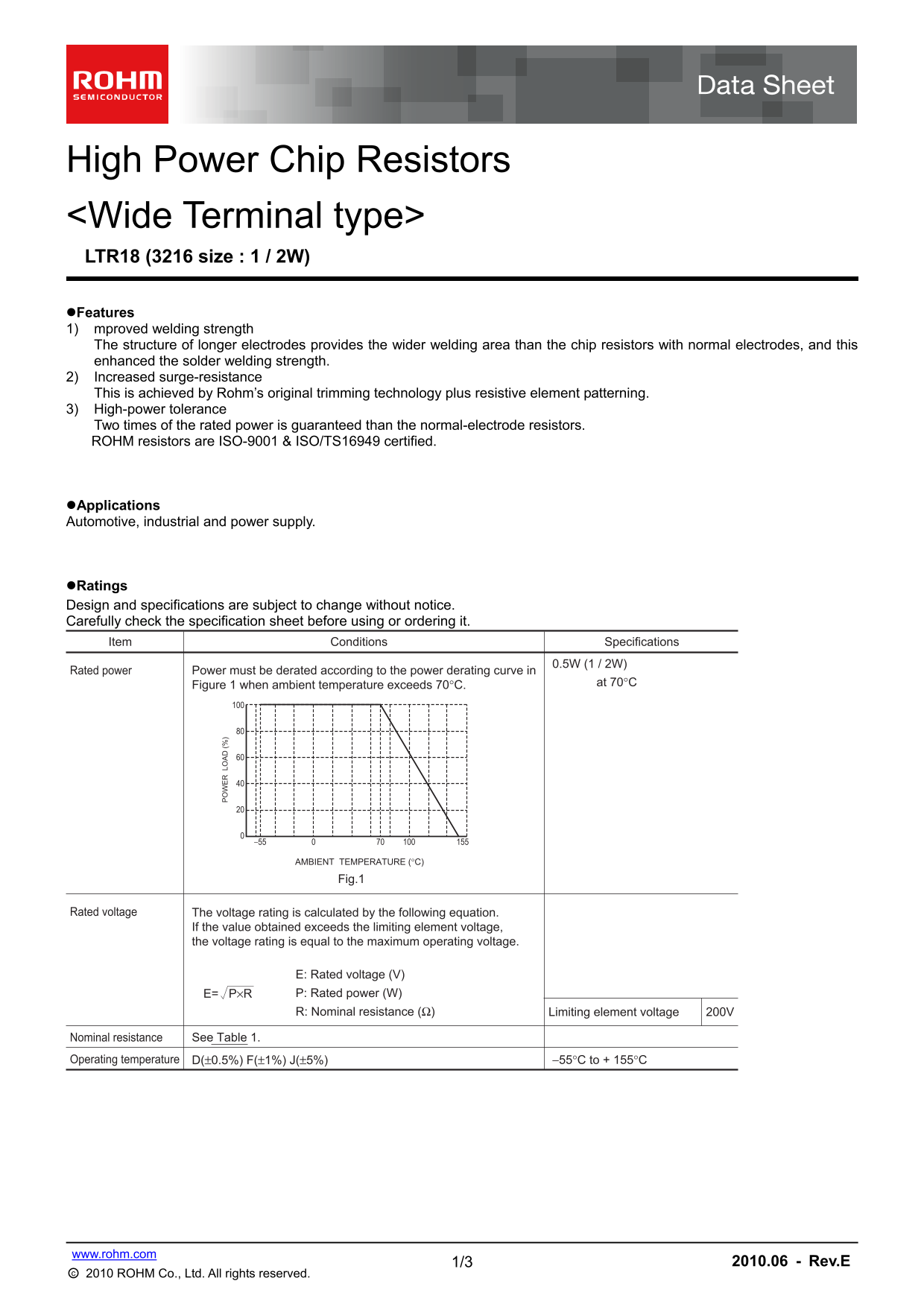
Rated power Power must be derated according to the power derating curve in
Figure 1 when ambient temperature exceeds 70°C. at 70°C
AMBIENT TEMPERATURE (°C)
Fig.1
Rated voltage The voltage rating is calculated by the following equation.
If the value obtained exceeds the limiting element voltage, the voltage rating is equal to the maximum operating voltage.
E: Rated voltage (V) E= P×R P: Rated power (W) R: Nominal resistance (Ω) Limiting element voltage 200V
Nominal resistance See Table 1.
Operating temperature D(±0.5%) F(±1%) J(±5%) −55°C to + 155°C
www.rohm.com
1/3 2010.06 - Rev.E
○c 2010 ROHM Co., Ltd. All rights reserved.
Page Summary Contents For ROHM LTR18EZPF User Guide and Manual
Manual Details
| Brand | ROHM |
|---|---|
| Pages | 3 |
| File Size | 114.18 KB |
| Published | July 22, 2026 |
Enter the captcha to get the download link:

Frequently Asked Questions
How is current overloads calculated for rating?
The maximum overload voltage capacity can be determined by testing at a rated power of 1.5kΩ, or using the specified test voltage (3kV).
What must I consider when operating in high temperatures?
If the ambient temperature exceeds 70°C, the rated power must be derated following the curve provided in Figure 1.
Does the resistor handle transient or pulse loads?
Yes, however, users must evaluate component performance while mounted when exposed to transients like pulse loads.
How do I determine if the correct voltage rating is used?
Calculate E = P × R; this value cannot exceed the specified limiting element voltage of 200V.