ROHM ES6U41 Data Sheet
Summary
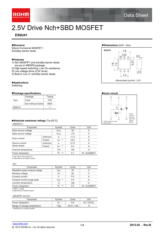
The ES6U41 is an efficient N-channel MOSFET packaged with a Schottky barrier diode ($\text{Nch+SBD}$), designed for high-speed switching applications. Engineered for low on-resistance and compatible with low 2.5V drive signals, this component ensures optimal performance in power circuits requiring reliable conversion. This manual provides comprehensive technical data, including absolute maximum ratings, detailed electrical characteristics curves, and application guidelines. It is essential reading for engineers developing various electronic equipment, such as communication or audio devices, needing efficient switching solutions.
Page 1 Text Content
2.5V Drive Nch+SBD MOSFET ES6U41 Structure Dimensions (Unit : mm) Silicon N-channel MOSFET /
WEMT6
Schottky barrier diode
Features 1) Nch MOSFET and schottky barrier diode- are put in WEMT6 package. 2) High-speed switching, Low On-resistance.
3) Low voltage drive (2.5V drive). (1) (2) (3)
4) Built-in Low VF schottky barrier diode.
Abbreviated symbol : U41
Applications Switching
Package specifications Inner circuit
Package Taping (6) (4)(5)
Type Code T2R
Basic ordering unit (pieces)
ES6U41
(1)Gate ∗1 (2)Source (3)Anode (1) (2) (3) (4)Cathode Absolute maximum ratings (Ta=25C) (5)Drain
∗1 ESD protection diode
(6)Drain
∗2 Body diode
<MOSFET>
Parameter Symbol Limits Unit
Drain-source voltage VVDSS
Gate-source voltage ±12 VVGSS Continuous ±1.5 AID
Drain current
Pulsed ±6.0 AIDP Source current Continuous 0.75 AIS
(Body diode) ∗1
Pulsed 6.0 AISP
°CTch Channel temperature
∗2PDPower dissipation W / ELEMENT0.7
∗1 Pw≤10μs, Duty cycle≤1% ∗2 Mounted on a ceramic board
Parameter Symbol Limits Unit
Repetitive peak reverse voltage VVRM Reverse voltage VVR
Forward current 0.5 AIF
Forward current surge peak AIFSM Junction temperature Tj °C
∗2Power dissipation 0.5 W / ELEMENTPD
∗1 60Hz 1cycle ∗2 Mounted on ceramic board
<MOSFET and Di>
Parameter Symbol Limits Unit
Power dissipation 0.8 W / TOTALPD
Range of storage temperature −55 to +150 °CTstg
∗ Mounted on a ceramic board
www.rohm.com
1/4 2012.02 - Rev.B
○c 2012 ROHM Co., Ltd. All rights reserved.
Page Summary Contents For ROHM ES6U41 Data Sheet
Manual Details
| Brand | ROHM |
|---|---|
| Pages | 5 |
| File Size | 192.90 KB |
| Published | June 05, 2026 |
Enter the captcha to get the download link:

Frequently Asked Questions
What is the absolute maximum drain current capacity (Pulsed IDp)?
The pulsed drain current (IDp) can reach up to ±6.0 A.
Does this device incorporate a built-in Schottky barrier diode?
Yes, it features an integrated low VF Schottky barrier diode, which is also the body diode.
What voltage is required for sourcing power to the gate (VGS)?
The continuous absolute maximum rating for the gate-source overvoltage (VGSS) is ±12 V.
How is power dissipation calculated when using both MOSFET and diode?
For the combined use of the MOSFET and diode, the total power dissipation (PD) must not exceed 0.8 W.