ROHM EMF32 Data Sheet
Summary
Optimize your electronics design with efficient dual-transistor power management circuits housed in a single, compact package. This component significantly reduces mounting area and manufacturing cost by integrating two key switching functions. The comprehensive datasheet provides critical technical details, including absolute maximum ratings, electrical characteristics over various temperatures, and precise dimensional specifications. Ideal for engineers developing general electronics such as consumer appliances, communication devices, or office automation equipment needing reliable power switching solutions.
Page 1 Text Content
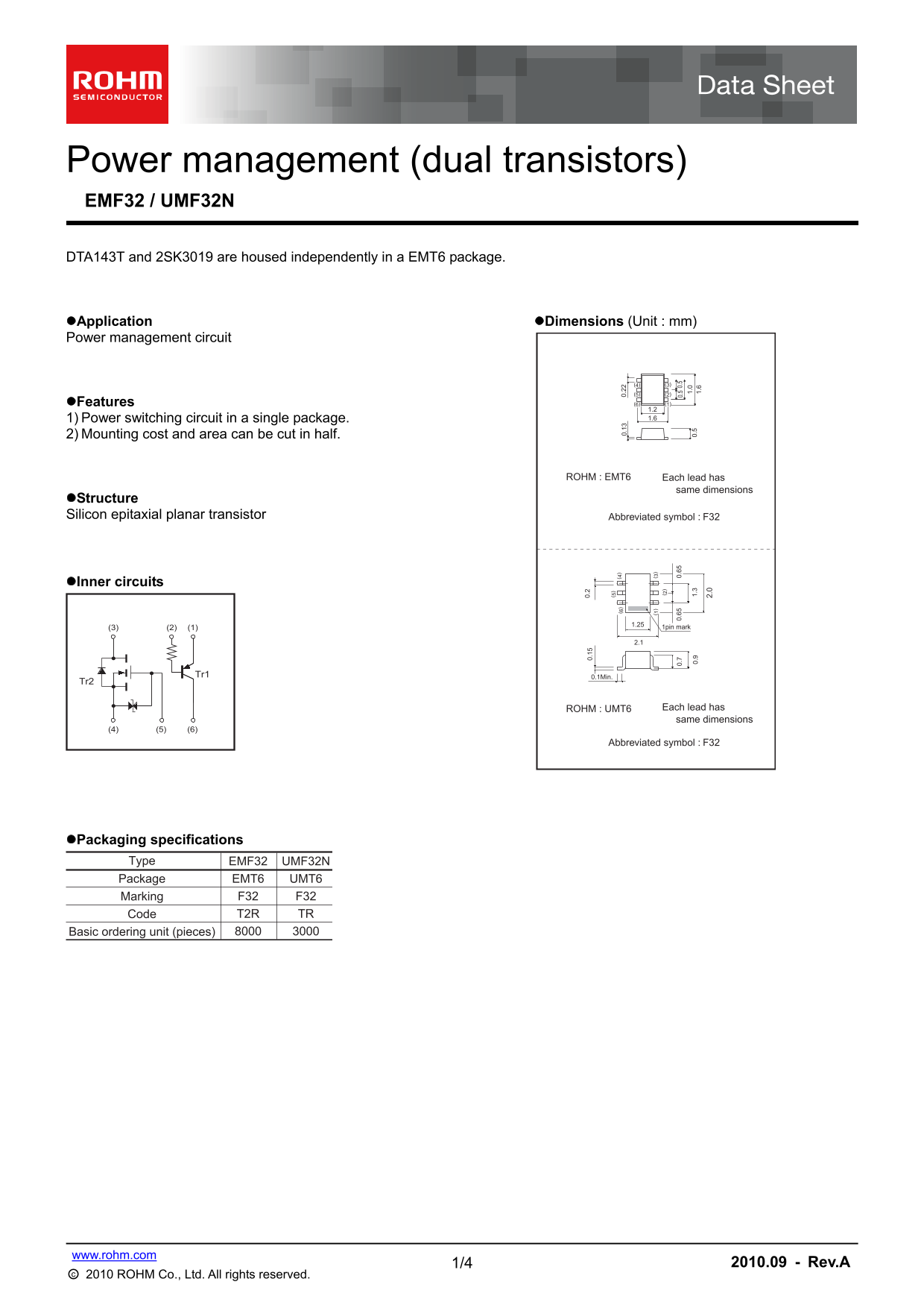
Power management (dual transistors) EMF32 / UMF32N DTA143T and 2SK3019 are housed independently in a EMT6 package.
Application Dimensions (Unit : mm) Power management circuit
Features (6) (1) 1.2 1) Power switching circuit in a single package. 1.6
2) Mounting cost and area can be cut in half.
ROHM : EMT6 Each lead has
same dimensions
Structure Silicon epitaxial planar transistor Abbreviated symbol : F32
Inner circuits
1.25 1pin mark 0. 0.
Tr1 0.1Min.
Tr2 0. 0. 0. 0. 0.
ROHM : UMT6 Each lead has 2. same dimensions
Abbreviated symbol : F32
Packaging specifications
Type EMF32 UMF32N Package EMT6 UMT6
Marking F32 F32 Code T2R TR
Basic ordering unit (pieces)
www.rohm.com
1/4 2010.09 - Rev.A
○c 2010 ROHM Co., Ltd. All rights reserved.
Page Summary Contents For ROHM EMF32 Data Sheet
Manual Details
| Brand | ROHM |
|---|---|
| Pages | 5 |
| File Size | 110.87 KB |
| Published | July 12, 2026 |
Enter the captcha to get the download link:

Frequently Asked Questions
How does this integrated package benefit design efficiency?
It combines the power switching circuit into a single package, which can cut both mounting cost and required area in half.
What is the absolute maximum safe voltage (VCBO) for Tr1?
The Collector-base voltage (VCBO) has an absolute maximum limit of -50 V.
Can this product be used in life-critical safety equipment, like aerospace machinery?
No. This product is not designed or manufactured for systems requiring extremely high reliability where failure could result in a direct threat to human life.
Are there special mounting requirements when installing the components?
Yes, each terminal must be mounted on a recommended land area.