ROHM EMD29 Data Sheet
Summary
The EMD29 is a reliable, isolated digital transistor solution designed for high-efficiency switching applications. Perfect for engineers developing motor drivers and DC/DC converters, this component features PNP (DTr1) and NPN (DTr2) configurations in an EMT6 package. This manual provides comprehensive technical documentation, including absolute maximum ratings, detailed electrical characteristics (Vce saturation, transition frequency), circuit constants, and operational curves to ensure accurate integration into your power electronics designs.
Page 1 Text Content
EMD29
Transistors
General purpose transistor (isolated transistors)
EMD29
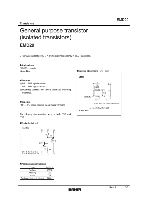
DTB513Z and DTC114E A are housed independently in a EMT6 package.
Applications DC / DC converter
Motor driver External dimensions (Unit : mm)
Features
1) DTr1 : PNP digital transistor 0.5
DTr2 : NPN digital transistor 0.50.5
2) Mounting possible with EMT3 automatic mounting (6) (5) (4)
machines.
1pin mark (1) (2) (3)
Structure
Each lead has same dimensions
PNP / NPN Silicon epitaxial planar digital transistor
Abbreviated symbol : D29
ROHM : EMT6
The following characteristics apply to both DTr1 and DTr2.
Equivalent circuit
EMD29
DTr1 : R1/R2 =1kΩ/10kΩ
DTr2 : R1/R2 =10kΩ/10kΩ (3)(2)(1)
Packaging specifications
Type EMD29
Package EMT6 Marking D29 Code T2R
Basic ordering unit (pieces)
Rev.A 1/5
Page Summary Contents For ROHM EMD29 Data Sheet
Manual Details
| Brand | ROHM |
|---|---|
| Pages | 6 |
| File Size | 121.67 KB |
| Published | June 18, 2026 |
Enter the captcha to get the download link:

Frequently Asked Questions
Can I use this transistor for life-critical equipment?
No, if your application requires an extremely high level of reliability and malfunction could endanger human life, you must consult a sales representative first.
What is the built-in resistance setup for the digital transistors?
The devices feature integrated resistors labeled R1 and R2, used in circuit constants to aid operation.
What are the absolute maximum total power dissipation limits?
For DTr1/DTr2 combined, the symbol Pd specifies a total power dissipation limit of 150 mW at Ta=25°C.