ROHM DTD113ZK DTD113ZU Data Sheet
Summary
Introducing the DTD113ZK/DTD113ZU transistor, an advanced NPN epitaxial planar silicon component featuring built-in bias resistors for simplified inverter circuits. This manual serves as a comprehensive technical resource for electronic engineers and circuit designers. It details crucial information, including absolute maximum ratings, electrical characteristics (like input/output voltage curves), and application guidelines, enabling reliable operation in various interfaces, drivers, and inverter design projects.
Page 1 Text Content
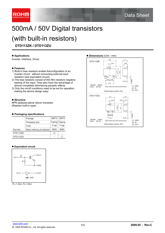
500m A / 50V Digital transistors (with built-in resistors) DTD113ZK / DTD113ZU Applications Dimensions (Unit : mm) Inverter, Interface, Driver 2.9 1.1
DTD113ZK
Features 1) Built-in bias resistors enable theconfiguration of an inverter circuit without connecting external input
resistors (see equivalent circuit). (2) (1) 2) The bias resistors consist of thin-film resistors negative 0.95 0.95
biasing of the input. They also have the advantage of 1.9
ROHM : SMT3
almost completely eliminat ing parasitic effects. (1) GND
EIAJ : SC-59 Each lead has same dimensions
3) Only the on/off conditions need to be set for operation, (2) IN (3) OUT
making the device design easy. Abbreviated symbol: G21
DTD113ZU
Structure 0.3 0.2 0.7
NPN epitaxial planar silicon transistor
(Resistor built-in type)
Packaging specifications
Package SMT3 UMT3 1.3
ROHM : UMT3 2.
Each lead has same dimensions 2. (1) GND
EIAJ : SC-70
Packaging type Taping Taping (2) IN
Abbreviated symbol: G21 (3) OUT
Code T146 T106
Part No. Basic ordering unit (pieces)
0. 3M in
0. 1M in
DTD113ZK DTD113ZU
Equivalent circuit
R1 OUT
IN OUT
www.rohm.com
1/3 2009.05 - Rev.C
○c 2009 ROHM Co., Ltd. All rights reserved.
Page Summary Contents For ROHM DTD113ZK DTD113ZU Data Sheet
Manual Details
| Brand | ROHM |
|---|---|
| Pages | 4 |
| File Size | 139.38 KB |
| Published | June 06, 2026 |
Enter the captcha to get the download link:

Frequently Asked Questions
How can I configure an inverter circuit using this device?
The built-in bias resistors enable the configuration of an inverter circuit without needing external input resistors.
What electrical limitations should I be aware of when operating the device?
The absolute maximum rated supply voltage (VCC) is 50 V, and the output current rating (IC) is 500 mA.
Can these transistors be used in life-critical systems like medical equipment?
No. They are not designed for use with any equipment requiring an extremely high level of reliability or where failure threatens human life.