ROHM BD6966NUX Data Sheet
Summary
The BD6966NUX is a robust single-phase full-wave motor driver integrated circuit optimized for fan motors, featuring soft switching and precise PWM speed control capabilities. This technical manual serves as a comprehensive resource detailing its operational parameters, electrical performance characteristics (including signal input levels and Hall bias), and physical integration guidelines. It provides critical information on absolute maximum ratings, necessary thermal design approaches, and safety cautions required for application in general-use electronic devices such as appliances and automation equipment.
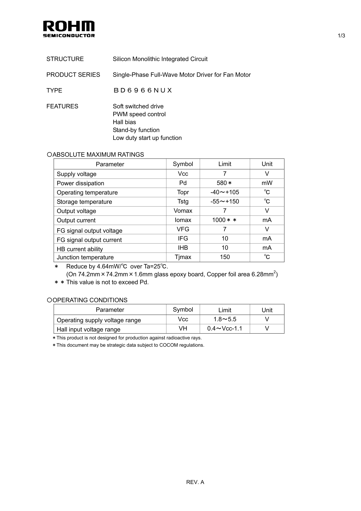
Page 1 Text Content
STRUCTURE Silicon Monolithic Integrated Circuit
PRODUCT SERIES Single-Phase Full-Wave Motor Driver for Fan Motor
TYPE BD6966NUX
FEATURES Soft switched drive PWM speed control Hall bias Stand-by function Low duty start up function
〇ABSOLUTE MAXIMUM RATINGS
Parameter Symbol Limit Unit
Supply voltage Vcc 7 V Power dissipation Pd 580* m W Operating temperature Topr -40~+105 ℃ Storage temperature Tstg -55~+150 ℃ Output voltage Vomax 7 V Output current Iomax 1000** m A FG signal output voltage VFG 7 V FG signal output current IFG 10 m A HB current ability IHB 10 m A Junction temperature Tjmax 150 ℃ * Reduce by 4.64m W/℃ over Ta=25℃. (On 74.2mm×74.2mm×1.6mm glass epoxy board, Copper foil area 6.28mm2) ** This value is not to exceed Pd.
〇OPERATING CONDITIONS
Parameter Symbol Limit Unit
Operating supply voltage range Vcc 1.8~5.5 V Hall input voltage range VH 0.4~Vcc-1.1 V *This product is not designed for production against radioactive rays. *This document may be strategic data subject to COCOM regulations.
REV. A
Page Summary Contents For ROHM BD6966NUX Data Sheet
Manual Details
| Brand | ROHM |
|---|---|
| Pages | 4 |
| File Size | 98.85 KB |
| Published | June 22, 2026 |
Enter the captcha to get the download link:

Frequently Asked Questions
What precautions should I take regarding power supply polarity?
Connecting the power supply in reverse polarity can damage the IC; take necessary precautions and consider adding an external direction diode.
How is the device meant to be used in terms of temperature?
The operating temperature range is -40 to +105 °C, but users must implement a thermal design with sufficient margin given the power dissipation (Pd).
What limits exist when exceeding absolute maximum ratings?
Exceeding any absolute maximum rating can break down the devices, making it impossible to identify the precise failure mode.
Does this product handle strong electromagnetic fields?
Use extreme caution when operating in a strong electromagnetic field because doing so may cause the IC to malfunction.