# A B C D E F G H I J K L M N O P Q R S T U V W X Y Z

ROHM BD6592MUV Data Sheet

Summary

Boost your displays using this high-efficiency white LED driver IC, ideal for powering middle to large LCD backlights in devices like notebooks and car navigation systems. This switching regulator provides precise PWM control and accurate current driving up to 40mA, ensuring uniform brightness across multiple LED strings and minimizing visible hotspots. The accompanying manual details comprehensive technical specifications, including wide operating voltage ranges (2.7V–22V), high efficiency rates, critical safety protections, and performance curves for reliable integration into diverse electronic equipment.
📄 Preview PAGE OF 26

Page 1 Text Content

LED Drivers for LCD Backlights

White Backlight LED Driver for Medium to Large LCD Panels (Switching Regulator Type)

BD6592MUV No.11040ECT33

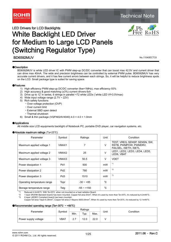
●Description BD6592MUV is white LED driver IC with PWM step-up DC/DC converter that can boost max 42.5V and current driver that can drive max 40m A. The wide and precision brightness can be controlled by external PWM pulse. BD6592MUV has very accurate current drivers, and it has few current errors between each strings. So, it will be helpful to reduce brightness spots on the LCD. Small package type is suited for saving space.

●Features 1) High efficiency PWM step-up DC/DC converter (fsw=1MHz), max efficiency 93% 2) High accuracy & good matching (±3%) current drivers 6ch 3) Drive up to 12* in series, 6 strings in parallel =72 white LEDs (*white LED Vf=3.5Vmax) 4) Wide input voltage range (2.7V ~ 22V) 5) Rich safety functions ・Over-voltage protection (OVP) ・Over current limit ・External SBD open detect ・Thermal shutdown 6) Small & thin package (VQFN024V4040) 4.0 × 4.0 × 1.0mm

●Applications All middle size LCD equipments backlight of Notebook PC, portable DVD player, car navigation systems, etc.

●Absolute maximum ratings (Ta=25℃)

Parameter Symbol Ratings Unit Condition

TEST, VREG, SENSP, SENSN, SW, Maximum applied voltage 1 VMAX1 7 V RSTB, PWMPOW, PWMDRV, FAILSEL, ISETH, ISETL

Maximum applied voltage 2 VMAX2 25 V LED1, LED2, LED3, LED4, LED5,

LED6, VBAT

Maximum applied voltage 3 VMAX3 50.5 V VDET

Power dissipation 1 Pd1 500 m W *1

Power dissipation 2 Pd2 780 m W *2

Power dissipation 3 Pd3 1510 m W *3

Operating temperature range Topr -30 ~ +85 ℃

Storage temperature range Tstg -55 ~ +150 ℃ *1 Reduced 4.0m W/℃ With Ta>25℃ when not mounted on a heat radiation Board. *2 1 layer (ROHM Standard board) has been mounted. Copper foil area 0mm2, When it’s used by more than Ta=25℃, it’s reduced by 6.2m W/℃. *3 4 layer (JEDEC Compliant board) has been mounted. Copper foil area 1layer 6.28mm2, Copper foil area 2~4layers 5655.04mm2, When it’s used by more than Ta=25℃, it’s reduced by 12.1m W/℃.

●Recommended operating range (Ta=-30℃ ~ +85℃)

Ratings

Parameter Symbol Unit Condition

Min. Typ. Max.

Power supply voltage VBAT 2.7 12.0 22.0 V

www.rohm.com 2011.06 - Rev.C

© 2011 ROHM Co., Ltd. All rights reserved.

Page Summary Contents For ROHM BD6592MUV Data Sheet

Page 1 LED Drivers for LCD Backlights White Backlight LED Driver for Medium to Large LCD Panels (Switching Regulator Type) BD6592MUV No.11040ECT33 ●Description BD6592MUV is white LED driver IC with PWM step-...
Page 2 BD6592MUV Technical Note ●Electrical characteristic (Unless otherwise specified, VBAT=12V, RSTB=2.5V, Ta = +25℃) Limits Parameter Symbol Unit Condition Min. Typ. Max. [FAILSEL,PWMDRV Terminal] EN thre...
Page 3 BD6592MUV Technical Note Iin [m A] LE ur re nt (m A) LE ur re nt (m A) ●Reference data VB AT [V VBAT [V] VBAT[V] VBAT [V] Fig.1 Fig.2 Fig.3 LE ur re nt (m A) Ef fic ie nc LE ur re nt (m A) Current Con...
Page 4 BD6592MUV Technical Note ur re nt at ch in ur re nt at ch in LE ur re nt [m A] PWMDRV Max Matching = Max LED Current/Average Current Max Matching = Max LED Current/Average Current 1.0 1.0 VOUT LED Cur...
Page 5 BD6592MUV Technical Note ●Block diagram, I/O equivalent circuit diagram VBAT VREG VBAT VREG VBAT 300kΩ VIN detector UVLO PWMPOW REG Internal Power suplly 500kΩ VDET PIN PIN PIN SBD Open protect FAILSE...
Page 6 BD6592MUV Technical Note ●Application example Battery Battery 10μF 4.7μH 10LED x 6parallel 10μF 4.7μH 10LED x 4aprallel RTR020N05 SW RTR020N05 SW FAILSEL FAILSEL VDET VDET SENSP SENSP SENSN SENSN Powe...
Page 7 BD6592MUV Technical Note ●Description of Functions 1) PWM current mode DC/DC converter While BD6592MUV is power ON, the lowest voltage of LED1, 2, 3, 4, 5, 6 is detected, PWM duty is decided to be 0.5...
Page 8 BD6592MUV Technical Note 4) External SBD open detect and over voltage protection BD6592MUV has over boost protection by external SBD open and over voltage protection. It detects VDET voltage and is st...
Page 9 BD6592MUV Technical Note (Example 1) In case of, VIN=6.5V, L=4.7µH, fsw=1MHz, VOUT=39V, IOUT=80m A, Efficiency=85% Ipeak = (6.5V / 4.7µH) × (1 / 1MHz) × (1-(6.5V / 39V)) =1.08A Iave = (39V × 80m A / 6...
Page 10 BD6592MUV Technical Note ●Attendance point of the restriction resistance input to RSTB When the restriction resistance is input to RSTB, it is necessary to +100℃ consider the input current of RSTB. +8...
Page 11 BD6592MUV Technical Note ●Start to use PWMPOW terminal for the PWM control, PWM operating After RSTB and PWMDRV is changing L  H, input PWM to PWMPOW terminal. There is no constraint in turn of RSTB ...
Page 12 BD6592MUV Technical Note ●Start to use PWMDRV terminal for the PWM control, PWM operating After RSTB and PWMPOW is changing L  H, input PWM to PWMDRV terminal. There is no constraint in turn of RSTB ...
Page 13 BD6592MUV Technical Note ●Brightness control There are two dimming method is available, first method is analog dimming that apply analog voltage to ISET terminal, and second method is PWM control via ...
Page 14 BD6592MUV Technical Note ●LED current setting range LED current can set up Normal and Starting setting current. LED current can set up Normal current by resistance value (RISETH) connecting to ISETH v...
Page 15 BD6592MUV Technical Note ●The coil selection The DC/DC is designed by more than 4.7µH. When L value sets to a lower value, it is possibility that the specific sub-harmonic oscillation of current mode ...
Page 16 BD6592MUV Technical Note ●Recommended PCB layout pattern BD6592MUV RISET RSENSE Fig.43 Frontal surface <Top view> Fig.44 Rear surface <Top view> www.rohm.com 2011.06 - Rev.C © 2011 ROHM Co...
Page 17 BD6592MUV Technical Note ●Selection of external parts Recommended external parts are as shown below. When to use other parts than these, select the following equivalent parts. ・Coil Value Manufacturer...
Page 18 BD6592MUV Technical Note ●Application example ・LED current setting controlled ISETH resistor. 24kΩ : 20m A 16kΩ : 30m A 12kΩ : 40m A ・Brightness control Please input PWM pulse from PWMPOW or PWMDRV te...
Page 19 BD6592MUV Technical Note ●Application example ・LED current setting controlled ISETH resistor. 24kΩ : 20m A 16kΩ : 30m A 12kΩ : 40m A ・Brightness control Please input PWM pulse from PWMPOW or PWMDRV te...
Page 20 BD6592MUV Technical Note ●Application example ・LED current setting controlled ISETH resistor. 24kΩ : 20m A 16kΩ : 30m A 12kΩ : 40m A ・Brightness control Please input PWM pulse from PWMPOW or PWMDRV te...
Page 21 BD6592MUV Technical Note ●Application example ・LED current setting controlled ISETH resistor. 24kΩ : 20m A 16kΩ : 30m A 12kΩ : 40m A ・Brightness control Please input PWM pulse from PWMPOW or PWMDRV te...
Page 22 BD6592MUV Technical Note ●Application example ・LED current setting controlled ISETH resistor. 24kΩ : 20m A 16kΩ : 30m A 12kΩ : 40m A ・Brightness control Please input PWM pulse from PWMPOW or PWMDRV te...
Page 23 BD6592MUV Technical Note ●Application example of Analog dimming Control LED current to charged D/A voltage. Show application example and typ control. Please decide final value after you evaluated appl...
Page 24 BD6592MUV Technical Note ●Notes for use (1) Absolute Maximum Ratings An excess in the absolute maximum ratings, such as supply voltage, temperature range of operating conditions, etc., can break down ...
Page 25 BD6592MUV Technical Note ●Ordering part number Part No. Part No. Package Packaging and forming specification MUV: VQFN024V4040 E2: Embossed tape and reel VQFN024V4040 4.0±0.1 <Tape and Reel informa...
Page 26 Notice No copying or reproduction of this document, in part or in whole, is permitted without the consent of ROHM Co.,Ltd. The content specified herein is subject to change for improvement without not...

Manual Details

Brand ROHM
Pages 26
File Size 827.02 KB
Published June 17, 2026
1 views

Enter the captcha to get the download link:

captcha

Frequently Asked Questions

What is the input voltage range for the BD6592MUV LED driver?

The recommended operating input voltage range is 2.7V to 22V.

How many LEDs can the BD6592MUV drive?

It can drive up to 12 in series and 6 strings in parallel, totaling 72 white LEDs.

What safety functions does the BD6592MUV include?

It has over-voltage protection, over current limit, external SBD open detect, and thermal shutdown.

What is the maximum output current per channel?

The maximum current per channel is 40mA with ±3% accuracy matching.