# A B C D E F G H I J K L M N O P Q R S T U V W X Y Z

ROHM BD64550EFV Data Sheet

Summary

Datasheet for the ROHM BD64550EFV system motor driver IC for inkjet printers, integrating 2-channel H-bridge driver, step-down switching regulator with built-in P-channel DMOS FET, series regulator, and reset output. Features low-on resistance outputs, constant-current chopping drive, soft start, 16-bit serial interface, overcurrent and thermal protection in HTSSOP-B40 package. Operates 7V to 36V with 8A peak motor current. Target users: printer hardware engineers and motor control designers developing inkjet printer mechanisms requiring integrated motor and power management.
📄 Preview PAGE OF 17

Page 1 Text Content

Motor Drivers for Printers

System Driver for Ink Jet Printers

No.10016EAT03

BD64550EFV

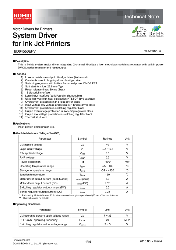
●Description This is 1-chip system motor driver integrating 2-channel H-bridge driver, step-down switching regulator with built-in power DMOS, series regulator and reset output.

●Features 1) Low-on resistance output H-bridge driver (2-channel) 2) Constant-current chopping drive H-bridge driver 3) Switching regulator with built-in P-channel power DMOS FET 4) Soft start function: 23.6 ms (Typ.) 5) Reset release timer: 80 ms (Typ.) 6) 16 bit serial interface 7) Logic input interface (serial/parallel changeable) 8) Ultra thin type high heat dissipation HTSSOP-B40 package 9) Overcurrent protection in H-bridge driver block 10) Input voltage low voltage protection in H-bridge driver block 11) Overcurrent protection in switching regulator block 12) Output overvoltage protection in switching regulator block 13) Output low voltage protection in switching regulator block 14) Thermal shutdown

●Applications Inkjet printer, photo printer, etc.

●Absolute Maximum Ratings (Ta=25℃)

Parameter Symbol Ratings Unit

VM applied voltage VM 40 V Logic input voltage VL -0.4 ~ 5.5 V RIN applied voltage VRIN 5.5 V RNF voltage VRNF 0.5 V Power dissipation Pd 1600* m W Operating temperature range TOPR -25 ~ +85 ℃ Storage temperature range TSTG -55 ~ +150 ℃ Junction temperature Tjmax 150 ℃ Motor driver output current (peak 500 ns) Iomax (peak) 8.0 A Motor driver output current (DC) Iomax (DC) 2.5** A Switching regulator output current (DC) Iomax 0.5 A Series regulator output current (DC) Iomax 0.25 A * Reduced by 12.8 m W/℃ over 25 ℃, when mounted on a glass epoxy board (70 mm x 70 mm x 1.6 mm). ** Must not exceed Pd or ASO.

●Operating Conditions

Parameter Symbol Limit Unit

VM operating power supply voltage range VM 7 ~ 36 V SCLK max. operating frequency FSCLK 20 MHz Switching regulator output voltage range Vswreg 3 ~ 5 V

www.rohm.com 2010.06 - Rev.A

© 2010 ROHM Co., Ltd. All rights reserved.

Page Summary Contents For ROHM BD64550EFV Data Sheet

Page 1 Motor Drivers for Printers System Driver for Ink Jet Printers No.10016EAT03 BD64550EFV ●Description This is 1-chip system motor driver integrating 2-channel H-bridge driver, step-down switching regula...
Page 2 BD64550EFV Technical Note ●Electrical Characteristics (Unless otherwise specified,Ta=25℃,VM=24V) Limit Parameter Symbol Unit Conditions Min. Typ. Max. Overall VM current 1 IVM1 - - 8 m A VM=7V VM curr...
Page 3 BD64550EFV Technical Note ut pu t L ol ta ge :V L[ ut pu t H ol ta ge :V [V ou t v ol ta ge :[V ir cu it cu rr en t : Ic c[ ●Reference Data Supply voltage :VM[V] Temperature [℃] Temperature (℃) ut pu ...
Page 4 BD64550EFV Technical Note ●Block Diagram, Application Circuit Diagram, and Pin Function Be sure to use VM1,VM2.VM3 and VM4 by short-circuit. VM1 VM2 OUT2P OUT1P Pre Pre driver driver Io1=(VREF1/10)・(1...
Page 5 BD64550EFV Technical Note ●Pin selection function Either serial control or external PWM control can be selected for motor control type with SELECT pin (pin 22). SELECT Output state L Serial input mode...
Page 6 BD64550EFV Technical Note ●Serial interface 16-bit 3-linear type serial interface (SDATA (pin 26), SCLK (pin 27), STROBE (pin 25)) is provided to set the operation and the value of current limit. Data...
Page 7 BD64550EFV Technical Note ●Serial Port Explanation WORD_S ○SWOFF Set on/off of switching regulator circuit. 0 Switching regulator on 1 Switching regulator off ○MASK SELECT Common mask can be provided ...
Page 8 BD64550EFV Technical Note ●H-bridge Driver Operation This IC has built-in 2-channel H-bridge driver. Each can be used for DC motor drive independently. 1. Current setting Motor output current-limit va...
Page 9 BD64550EFV Technical Note ●Switching regulator operation ○Basic operation A switching regulator circuit that repeats on/off being synchronized with internal CLK (200 KHz) is built-in. The start up out...
Page 10 BD64550EFV Technical Note ○Soft start As shown in Fig.24, VOUTDCDC output voltage becomes up and run step by step with soft start at the time of power-on. VM voltage VMPORH CLK195 Oscillation (Interna...
Page 11 BD64550EFV Technical Note ●Protection function ○Protection circuit function Overall Overheating protection DC motor drive circuit Overcurrent protection Switching regulator circuit Overcurrent protect...
Page 12 BD64550EFV Technical Note ④Low voltage protection/overvoltage protection circuit All functions are shutout on the condition of setting value (+30%, -30%) while DSEN pin voltage (pin 18) of switching r...
Page 13 BD64550EFV Technical Note ●I/O Circuit Diagram ① OUT1P, OUT1M, OUT2P, OUT2M, RNF1 and RNF2 ② RNF1S and RNF2S VM1, VM2 OUT1P, OUT2P OUT1M, OUT2M RNF1S, RNF2S Overcurrent protection circuit RNF1, RNF2 1...
Page 14 BD64550EFV Technical Note ●Power Dissipation Reduction On the backside of HTSSOP-B40 package, metal is filled in. Heat dissipation is possible by letting in a through hole from backside. Power dissipa...
Page 15 BD64550EFV Technical Note 5) Setting of heat Use a thermal design that allows for a sufficient margin in light of the power dissipation (Pd) in actual operating conditions. BD64550EFV expose its frame...
Page 16 BD64550EFV Technical Note ●Ordering Part Number 1. 0M ax 7. 8± 0. Part No. Part No. Package Packaging and forming specification EFV : HTSSOP-B40 E2: Embossed tape and reel HTSSOP-B40 <Tape and Reel...
Page 17 Notice No copying or reproduction of this document, in part or in whole, is permitted without the consent of ROHM Co.,Ltd. The content specified herein is subject to change for improvement without not...

Manual Details

Brand ROHM
Pages 17
File Size 397.47 KB
Published June 16, 2026
1 views

Enter the captcha to get the download link:

captcha

Frequently Asked Questions

What is the maximum supply voltage for the BD64550EFV motor driver?

The maximum applied voltage (VM) is 40V.

How many H-bridge motor channels does this driver have?

It has two independent H-bridge driver channels.

What is the typical reset release timer delay?

The typical reset release timer delay is 80 ms.

What is the switching regulator's output voltage range?

The switching regulator output voltage range is 3V to 5V.