# A B C D E F G H I J K L M N O P Q R S T U V W X Y Z

ROHM BD6370GUL Data Sheet

Summary

These specialized System Lens Drivers are essential components engineered for modern digital still cameras and single-lens reflex systems. They provide precise motor control via advanced H-bridge channels for functions like auto focus (stepping motors) and zoom/iris adjustments (DC motors). The manual details comprehensive technical specifications, including absolute maximum ratings, built-in high-precision D/A converters, and multiple operating modes for system integration. This resource is ideal for electronics engineers developing professional camera equipment that requires accurate, reliable motor actuation.
📄 Preview 📖 Table of Contents Contents PAGE OF 33

Page 1 Text Content

System Lens Driver for Digital Still Cameras / Single-lens Reflex Cameras

5ch System Lens Drivers for Digital Still Cameras BD6370GUL, BD6758MWV, BD6758KN

No.09014EAT01

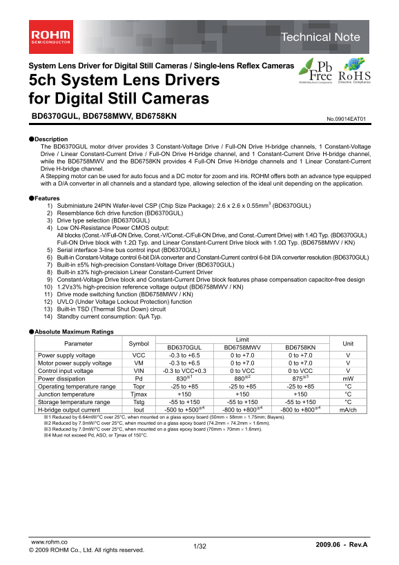
●Description The BD6370GUL motor driver provides 3 Constant-Voltage Drive / Full-ON Drive H-bridge channels, 1 Constant-Voltage Drive / Linear Constant-Current Drive / Full-ON Drive H-bridge channel, and 1 Constant-Current Drive H-bridge channel, while the BD6758MWV and the BD6758KN provides 4 Full-ON Drive H-bridge channels and 1 Linear Constant-Current Drive H-bridge channel. A Stepping motor can be used for auto focus and a DC motor for zoom and iris. ROHM offers both an advance type equipped with a D/A converter in all channels and a standard type, allowing selection of the ideal unit depending on the application.

●Features 1) Subminiature 24PIN Wafer-level CSP (Chip Size Package): 2.6 x 2.6 x 0.55mm3 (BD6370GUL) 2) Resemblance 6ch drive function (BD6370GUL) 3) Drive type selection (BD6370GUL) 4) Low ON-Resistance Power CMOS output: All blocks (Const.-V/Full-ON Drive, Const.-V/Const.-C/Full-ON Drive, and Const.-Current Drive) with 1.4Ω Typ. (BD6370GUL) Full-ON Drive block with 1.2Ω Typ. and Linear Constant-Current Drive block with 1.0Ω Typ. (BD6758MWV / KN) 5) Serial interface 3-line bus control input (BD6370GUL) 6) Built-in Constant-Voltage control 6-bit D/A converter and Constant-Current control 6-bit D/A converter resolution (BD6370GUL) 7) Built-in ±5% high-precision Constant-Voltage Driver (BD6370GUL) 8) Built-in ±3% high-precision Linear Constant-Current Driver 9) Constant-Voltage Drive block and Constant-Current Drive block features phase compensation capacitor-free design 10) 1.2V±3% high-precision reference voltage output (BD6758MWV / KN) 11) Drive mode switching function (BD6758MWV / KN) 12) UVLO (Under Voltage Lockout Protection) function 13) Built-in TSD (Thermal Shut Down) circuit 14) Standby current consumption: 0μA Typ.

●Absolute Maximum Ratings

Limit

Parameter Symbol Unit

BD6370GUL BD6758MWV BD6758KN

Power supply voltage VCC -0.3 to +6.5 0 to +7.0 0 to +7.0 V Motor power supply voltage VM -0.3 to +6.5 0 to +7.0 0 to +7.0 V Control input voltage VIN -0.3 to VCC+0.3 0 to VCC 0 to VCC V Power dissipation Pd 830※1 880※2 875※3 m W Operating temperature range Topr -25 to +85 -25 to +85 -25 to +85 °C Junction temperature Tjmax +150 +150 +150 °C Storage temperature range Tstg -55 to +150 -55 to +150 -55 to +150 °C H-bridge output current Iout -500 to +500※4 -800 to +800※4 -800 to +800※4 m A/ch ※1 Reduced by 6.64m W/°C over 25°C, when mounted on a glass epoxy board (50mm  58mm  1.75mm; 8layers). ※2 Reduced by 7.0m W/°C over 25°C, when mounted on a glass epoxy board (74.2mm  74.2mm  1.6mm). ※3 Reduced by 7.0m W/°C over 25°C, when mounted on a glass epoxy board (70mm  70mm  1.6mm). ※4 Must not exceed Pd, ASO, or Tjmax of 150°C.

www.rohm.co

2009.06 - Rev.A

© 2009 ROHM Co., Ltd. All rights reserved.

Page Summary Contents For ROHM BD6370GUL Data Sheet

Page 1 System Lens Driver for Digital Still Cameras / Single-lens Reflex Cameras 5ch System Lens Drivers for Digital Still Cameras BD6370GUL, BD6758MWV, BD6758KN No.09014EAT01 ●Description The BD6370GUL moto...
Page 2 BD6370GUL, BD6758MWV, BD6758KN Technical Note ●Operating Conditions (Ta=-25 to +85°C) Limit Unit Parameter Symbol BD6370GUL BD6758MWV BD6758KN Power supply voltage VCC 2.7 to 5.5 2.5 to 5.5 2.5 to 5.5...
Page 3 BD6370GUL, BD6758MWV, BD6758KN Technical Note iff . n -li to le ra ce ID [L iff . n -li to le ra ce ID [L iff . n on -li ne ar to le ra nc : D [L irc ui cu rr en IC 2) BD6370GUL Electrical DC Characte...
Page 4 BD6370GUL, BD6758MWV, BD6758KN Technical Note 3) BD6370GUL Electrical AC Characteristics (Unless otherwise specified, Ta=25°C, VCC=3.0V, VM=5.0V) Constant-Voltage / Full-ON Type Drive blocks (ch1 to c...
Page 5 BD6370GUL, BD6758MWV, BD6758KN Technical Note 4) BD6370GUL Electrical AC Characteristic Diagrams BD6370GUL BD6370GUL BD6370GUL INPUT1,2,or34 INPUT1,2,or34 INPUT34or45 voltage voltage voltage [5V/div] ...
Page 6 BD6370GUL, BD6758MWV, BD6758KN Technical Note BD6370GUL BD6370GUL INPUT34or45 voltage [5V/div] OUT4A-4B OUT5A-5B current current [200m A/div] [200m A/div] [500nsec/div] [500nsec/div] Fig.26 I/O AC Res...
Page 7 BD6370GUL, BD6758MWV, BD6758KN Technical Note is si tio lta irc ui cu rr en IC 6) BD6758MWV and BD6758KN Electrical AC Characteristic Diagrams BD6758MWV, BD6758KN BD6758MWV, BD6758KN BD6758MWV, BD6758...
Page 8 BD6370GUL, BD6758MWV, BD6758KN Technical Note ●Block Diagram, Pin Arrangement, and Pin Function VCC E3 PS B3 Power Save & Serial Reset Band Gap TSD & UVLO A4 OUT1A Serial Interface H bridge IN...
Page 9 BD6370GUL, BD6758MWV, BD6758KN Technical Note PS Power Save Band Gap TSD & UVLO 35 VM1 31 OUT1A IN1A H bridge Level Shift Full ON IN1B OUT1B Logic12 IN2A OUT2A Pre Driver H bridge IN2B Full ON OUT...
Page 10 BD6370GUL, BD6758MWV, BD6758KN Technical Note ●BD6370GUL Function Explanation Bypass filter Capacitor for power supply input. (p.29/32) Power-saving (p.11/32) 1~100u F H : Active VCC L : Standby E3 PS...
Page 11 BD6370GUL, BD6758MWV, BD6758KN Technical Note 1) Power-saving and Serial Reset (BD6370GUL; PS) (1) Function Explanation When Low-level voltage is applied to PS pin, the IC will be turned off internall...
Page 12 BD6370GUL, BD6758MWV, BD6758KN Technical Note 4) Serial Input (BD6370GUL; STROBE, SCLK, and SDATA) (1) Function Explanation The BD6370GUL provides a 3-line serial interface for setting output modes an...
Page 13 BD6370GUL, BD6758MWV, BD6758KN Technical Note 5) Serial Register Data Bit Function (BD6370GUL) (1) ADDRESS BIT [000] Function Explanation ADDRESS BIT DATA BIT No. Bit[E] Bit[D] Bit[C] Bit[B] Bit[A] Bi...
Page 14 BD6370GUL, BD6758MWV, BD6758KN Technical Note (d) MODE45, MODE34; input terminal select for ch3, ch4, and ch5, and MODE23, MODE13; resemblance drive select for ch1, ch2, and ch3 Bit[9] Bit[8] Bit[7] B...
Page 15 BD6370GUL, BD6758MWV, BD6758KN Technical Note (2) ADDRESS BIT [001] Function Explanation ADDRESS BIT DATA BIT No. Bit[E] Bit[D] Bit[C] Bit[B] Bit[A] Bit[9] Bit[8] Bit[7] Bit[6] Bit[5] Bit[4] Bit[3] Bi...
Page 16 BD6370GUL, BD6758MWV, BD6758KN Technical Note (3) ADDRESS BIT [010] Function Explanation ADDRESS BIT DATA BIT No. Bit[E] Bit[D] Bit[C] Bit[B] Bit[A] Bit[9] Bit[8] Bit[7] Bit[6] Bit[5] Bit[4] Bit[3] Bi...
Page 17 BD6370GUL, BD6758MWV, BD6758KN Technical Note (b) DAC3[5] to DAC3[0]; D/A Converter setting for output high voltage of Constant-Voltage mode in ch3 Bit[5] Bit[4] Bit[3] Bit[2] Bit[1] Bit[0] DAC3 setti...
Page 18 BD6370GUL, BD6758MWV, BD6758KN Technical Note (4) ADDRESS BIT [011] Function Explanation ADDRESS BIT DATA BIT No. Bit[E] Bit[D] Bit[C] Bit[B] Bit[A] Bit[9] Bit[8] Bit[7] Bit[6] Bit[5] Bit[4] Bit[3] Bi...
Page 19 BD6370GUL, BD6758MWV, BD6758KN Technical Note (b) DACI4[5] to DACI4[0]; D/A Converter setting for output current (DACI4 setting voltage) of Constant-Current mode in ch4 As regards how to calculate the...
Page 20 BD6370GUL, BD6758MWV, BD6758KN Technical Note (5) ADDRESS BIT [100] Function Explanation ADDRESS BIT DATA BIT No. Bit[E] Bit[D] Bit[C] Bit[B] Bit[A] Bit[9] Bit[8] Bit[7] Bit[6] Bit[5] Bit[4] Bit[3] Bi...
Page 21 BD6370GUL, BD6758MWV, BD6758KN Technical Note 6) I/O Truth Table (BD6370GUL) (1) I/O truth table for ch1 and ch2, in the case of MODE13=0, MODE23=0 (x=1 or 2) Serial interface input bit Terminal Outpu...
Page 22 BD6370GUL, BD6758MWV, BD6758KN Technical Note (3) I/O truth table for ch1, ch3, in the case of MODE13=1 (OUT1A-OUT3A resemblance drive mode) Serial interface input bit Terminal Output terminal MODE12B...
Page 23 BD6370GUL, BD6758MWV, BD6758KN Technical Note (5) I/O truth table for ch4, in the case of MODE45=0 (if MODE34=0, then x=45, else then x=34) Serial interface input bit Terminal Output terminal MODE4B M...
Page 24 BD6370GUL, BD6758MWV, BD6758KN Technical Note 7) The More Precise Constant-Current Settings (BD6370GUL) Regarding Constant-Current Drive blocks (ch4 and ch5), there is the metal impedance of each RNF ...
Page 25 BD6370GUL, BD6758MWV, BD6758KN Technical Note 8) Application control sequences (BD6370GUL) (1) Stepping Motor drive controlled by 2 phases mode STROBE SDATA (i) (ii) (iii) (iv) (v) (vi) (vii) INPUT1 I...
Page 26 BD6370GUL, BD6758MWV, BD6758KN Technical Note In Fig.49, it shows minimum step angle, and the relation between size and direction of the current to motor. CW OUT2A Forwar OUT1B OUT1A CCW CW OUT2B CCW ...
Page 27 BD6370GUL, BD6758MWV, BD6758KN Technical Note ●BD6758MWV and BD6758KN Function Explanation Bypass filter Capacitor for power supply input. (p.29/32) Power-saving (p.27/32) 1~100u F H : Active VCC Bypa...
Page 28 BD6370GUL, BD6758MWV, BD6758KN Technical Note 4) Drive system of Linear Constant-Current H-bridge (BD6758MWV / KN: ch5) BD6758MWV / KN (ch5) enable Linear Constant-Current Driving. (1) Reference volta...
Page 29 BD6370GUL, BD6758MWV, BD6758KN Technical Note ●I/O Circuit Diagram PS, INPUT1, 2, 34, 45※ VM, GND, VM, RNF4, OUT4A, 4B VM, RNF5, OUT5A, 5B STROBE, SCLK, SDATA※9 OUT1A, 1B, 2A, 2B, 3A, 3B VCC VCC VM VM...
Page 30 BD6370GUL, BD6758MWV, BD6758KN Technical Note 6) Pin short and wrong direction assembly of the device Use caution when positioning the IC for mounting on printed circuit boards. The IC may be damaged ...
Page 31 BD6370GUL, BD6758MWV, BD6758KN Technical Note ●Ordering part number Part No. Part No. Package Packaging and forming specification 6370 :C.V./F.ON 3ch GUL : VCSP50L2 E2: Embossed tape and reel +C.V./C....
Page 32 BD6370GUL, BD6758MWV, BD6758KN Technical Note VQFN36 6.2±0.1 <Tape and Reel information> Embossed carrier tape (with dry pack)Tape Quantity 2500pcs Direction The direction is the 1pin of product...
Page 33 Notice No copying or reproduction of this document, in part or in whole, is permitted without the consent of ROHM Co.,Ltd. The content specified herein is subject to change for improvement without not...

Manual Details

Brand ROHM
Pages 33
File Size 820.65 KB
Published June 06, 2026
63 views

Enter the captcha to get the download link:

captcha

Frequently Asked Questions

Which motors can be controlled by these drivers?

A stepping motor can be used for auto focus, and a DC motor can be used for zoom and iris.

What is the maximum output current rating for the BD6758 series?

The H-bridge output current (Iout) is rated from -800 to +800 mA/ch.

How do I select the proper driver model based on my application?

ROHM offers both advance types with a D/A converter and standard types, allowing selection of the ideal unit depending on your specific application.

What safety precautions must be implemented when using these drivers?

Due to potential failure risks, implement safety measures like derating, redundancy, fire control, and fail-safe designs. The products are not for use in life-critical systems.