# A B C D E F G H I J K L M N O P Q R S T U V W X Y Z

ROHM BD6210F Data Sheet

Summary

These high-efficiency BD621X H-bridge drivers provide precise, reliable motor control for various brush motor applications. Supporting output currents up to 2A and working within a flexible 3.0V to 5.5V range, they integrate advanced PWM signal control (20kHz–100kHz) and critical protection circuits (OCP/OVP). Ideal for embedding in audio-visual equipment, CD/DVD players, and optical disc drives, the manual details operational specifications and performance curves necessary for professional system integration.
📄 Preview PAGE OF 14

Page 1 Text Content

H-bridge Drivers for Brush Motors

7V Max. H-bridge Drivers BD621X Series No.11007EDT01

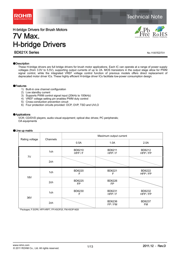
●Description These H-bridge drivers are full bridge drivers for brush motor applications. Each IC can operate at a range of power supply voltages (from 3.0V to 5.5V), supporting output currents of up to 2A. MOS transistors in the output stage allow for PWM signal control, while the integrated VREF voltage control function of previous models offers direct replacement of deprecated motor driver ICs. These highly efficient H-bridge driver ICs facilitate low-power consumption design.

●Features 1) Built-in one channel configuration 2) Low standby current 3) Supports PWM control signal input (20k Hz to 100k Hz) 4) VREF voltage setting pin enables PWM duty control 5) Cross-conduction prevention circuit 6) Four protection circuits provided: OCP, OVP, TSD and UVLO

●Applications VCR; CD/DVD players; audio-visual equipment; optical disc drives; PC peripherals; OA equipments

●Line up matrix

Maximum output current

Rating voltage Channels

BD6210 BD6211 BD6212

HFP / F HFP / F HFP / FP

BD6221 BD6222

1ch BD6220

HFP / FP

BD6226

2ch BD6225

FP FP

BD6230 BD6231 BD6232

HFP / F HFP / FP

BD6237

2ch BD6236

FP / FM FM

*Packages; F:SOP8, HFP:HRP7, FP:HSOP25, FM:HSOP-M28

www.rohm.com 2011.12 - Rev.D

© 2011 ROHM Co., Ltd. All rights reserved.

Page Summary Contents For ROHM BD6210F Data Sheet

Page 1 H-bridge Drivers for Brush Motors 7V Max. H-bridge Drivers BD621X Series No.11007EDT01 ●Description These H-bridge drivers are full bridge drivers for brush motor applications. Each IC can operate at ...
Page 2 BD621X Series Technical Note ●Absolute maximum ratings (Ta=25℃, All voltages are with respect to ground) Parameter Symbol Ratings Unit Supply voltage VCC 7 V Output current IOMAX 0.5 *1 / 1.0 *2 / 2.0...
Page 3 BD621X Series Technical Note In te rn al og ic /L irc ui ur re nt Ic [m sc ill at io re qu en cy FP k H z] In pu ia rr en t: IH ●Electrical characteristic curves (Reference data) Supply Voltage: Vcc [...
Page 4 BD621X Series Technical Note tp lta tp lta tp lta :V -V [V tp lta -V [V ●Electrical characteristic curves (Reference data) - Continued 0.4 0.8 0.8 0.1 0.2 0.3 0.4 0.5 0.2 0.4 0.6 0.8 0.4 0.8 1.2 1.6 O...
Page 5 BD621X Series Technical Note ●Block diagram and pin configuration BD6210F / BD6211F Table 1 BD6210F/BD6211F Pin Name Function 1 OUT1 Driver output 6 VREF DUTY PROTECT 2 VCC Power supply 3 VCC Power su...
Page 6 BD621X Series Technical Note ●Block diagram and pin configuration - Continued BD6212FP Table 3 BD6212FP 17 VREF DUTY PROTECT VCC Pin Name Function VCC 1,2 OUT1 Driver output 6 GND Small signal ground ...
Page 7 BD621X Series Technical Note ●Functional descriptions 1) Operation modes Table 4 Logic table FIN RIN VREF OUT1 OUT2 Operation a L L X Hi-Z* Hi-Z* Stand-by (idling) b H L VCC H L Forward (OUT1 > OUT...
Page 8 BD621X Series Technical Note e) f) PWM control mode A The rotational speed of the motor can be controlled by the switching duty when the PWM signal is input to the FIN pin or the RIN pin. In this mode...
Page 9 BD621X Series Technical Note i) j) VREF control mode The built-in VREF-switching on duty conversion circuit provides switching duty corresponding to the voltage of the VREF pin and the VCC voltage. Th...
Page 10 BD621X Series Technical Note d) Over current protection (OCP) circuit To protect this driver IC from ground faults, power supply line faults and load short circuits, the OCP circuit monitors the outpu...
Page 11 BD621X Series Technical Note ●Notes for use 1) Absolute maximum ratings Devices may be destroyed when supply voltage or operating temperature exceeds the absolute maximum rating. Because the cause of ...
Page 12 BD621X Series Technical Note 13) Regarding the input pin of the IC This monolithic IC contains P+ isolation and P substrate layers between adjacent elements, in order to keep them isolated. P-N juncti...
Page 13 BD621X Series Technical Note ●Ordering part number ROHM part number Type Package Packaging and forming specification BD 62XX F : SOP8 E2: Embossed taping 1X: 7V max. FP : HSOP25 (SOP8/HSOP25) (7 .4 9)...
Page 14 Notice No copying or reproduction of this document, in part or in whole, is permitted without the consent of ROHM Co.,Ltd. The content specified herein is subject to change for improvement without not...

Manual Details

Brand ROHM
Pages 14
File Size 381.62 KB
Published June 18, 2026
1 views

Enter the captcha to get the download link:

captcha

Frequently Asked Questions

What is the general operating voltage range for these H-bridge drivers?

The devices operate at a supply voltage (VCC) of 3.0 V to 5.5 V.

Does this device support PWM control and what are its frequency limits?

Yes, it supports PWM signal control input from 20 kHz to 100 kHz.

What safety features are included with the BD621X series?

It includes four protection circuits: OCP (overcurrent), OVP (overvoltage), TSD (thermal shutdown), and UVLO (undervoltage lock-out).

Can this IC be used for low-power consumption designs?

Yes, these highly efficient H-bridge driver ICs facilitate low-power consumption design.