# A B C D E F G H I J K L M N O P Q R S T U V W X Y Z

ROHM BD60910GU Data Sheet

Summary

This technical manual details the BD60910GU, an 8-channel LED driver IC featuring auto luminous control for mobile applications. Designed for small to medium LCD panels, it offers efficient DC/DC boost conversion, adjustable constant current, and PWM control to ensure optimal backlight performance.
📄 Preview PAGE OF 31

Page 1 Text Content

LED Drivers for LCD Backlights

White backlight LED Drivers for Small to Medium LCD Panels (Switching Regulator Type)

No.11040EBT30

BD60910GU

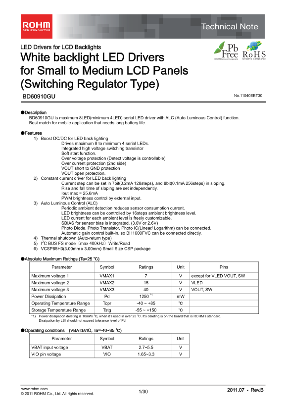
●Description BD60910GU is maximum 8LED(minimum 4LED) serial LED driver with ALC (Auto Luminous Control) function. Best match for mobile application that needs long battery life.

●Features 1) Boost DC/DC for LED back lighting Drives maximum 8 to minimum 4 serial LEDs. Integrated high voltage switching transistor Soft start function. Over voltage protection (Detect voltage is controllable) Over current protection (2nd side) VOUT short to GND protection VOUT open protection. 2) Constant current driver for LED back lighting Current step can be set in 7bit(0.2m A 128steps), and 8bit(0.1m A 256steps) in sloping. Rise and fall time of sloping are set independently. Iout max = 25.6m A PWM brightness control by external input. 3) Auto Luminous Control (ALC) Periodic ambient detection reduces sensor consumption current. LED brightness can be controlled by 16steps ambient brightness level. LED current for each ambient level is freely customizable. SBIAS for sensor bias is integrated. (3.0V or 2.6V) Photo Diode, Photo Transistor, Photo IC(Linear/ Logarithm) can be connected. Automatic gain control built-in, so BH1600FVC can be connected directly. 4) Thermal shutdown (Auto-return type) 5) I2C BUS FS mode(max 400k Hz)Write/Read 6) VCSP85H3(3.00mm x 3.00mm) Small Size CSP package

●Absolute Maximum Ratings (Ta=25 ℃)

Parameter Symbol Ratings Unit Pins

Maximum voltage 1 VMAX1 7 V except for VLED VOUT, SW Maximum voltage 2 VMAX2 15 V VLED Maximum voltage 3 VMAX3 40 V VOUT, SW Power Dissipation Pd 1250 *1 m W Operating Temperature Range Topr -40 ~ +85 ℃ Storage Temperature Range Tstg -55 ~ +150 ℃ *1) Power dissipation deleting is 10m W/ ℃, when it’s used in over 25 ℃. It’s deleting is on the board that is ROHM’s standard. Dissipation by LSI should not exceed tolerance level of Pd.

●Operating conditions (VBAT≥VIO, Ta=-40~85 ℃)

Parameter Symbol Ratings Unit

VBAT input voltage VBAT 2.7~5.5 V VIO pin voltage VIO 1.65~3.3 V

www.rohm.com 2011.07 - Rev.B

© 2011 ROHM Co., Ltd. All rights reserved.

Page Summary Contents For ROHM BD60910GU Data Sheet

Page 1 LED Drivers for LCD Backlights White backlight LED Drivers for Small to Medium LCD Panels (Switching Regulator Type) No.11040EBT30 BD60910GU ●Description BD60910GU is maximum 8LED(minimum 4LED) serial...
Page 2 BD60910GU Technical Note ●Electrical Characteristics (Unless otherwise specified, Ta=25°C, VBAT=3.6V, VIO=1.8V) Limits Parameter Symbol Unit Condition Min. Typ. Max. 【Circuit Current】 VBAT Circuit cur...
Page 3 BD60910GU Technical Note ●Electrical Characteristics (Unless otherwise specified, Ta=25°C, VBAT=3.6V, VIO=1.8V) Limits Parameter Symbol Unit Condition Min. Typ. Max. 【ALC】 2.850 3.0 3.150 V Io=200μA &...
Page 4 BD60910GU Technical Note ●Block Diagram / Application Circuit example VBAT RB520S-40 VBAT1 VBAT2 DC/DC ( ) ( ) ( ) RESETB Level I2C interface SDA I/O Shift Digital Control Feed Back WPWMIN External PW...
Page 5 BD60910GU Technical Note ●Pin Arrangement [Bottom View] T4 GND2 GNDP SW T3 VIO SCL RESETB GNDPS VBAT2 GND1 SDA VOUT GC2 SGND index WPWMIN GC1 SBIAS SSENS T1 VBAT1 LEDGND VLED T2 Fig.2 Pin Arrangement ...
Page 6 BD60910GU Technical Note ●Equivalent Circuit VBATCA VBATB E VIO VBAT H VIOVBAT I VBATVBATL VBAT M VBAT N VBAT VBATQ Vo S VBAT X VBATVBATS www.rohm.com 2011.07 - Rev.B © 2011 ROHM Co., Ltd. All rights ...
Page 7 BD60910GU Technical Note ●I2C BUS format The writing/reading operation is based on the I2C slave standard. ・ Slave address ・ Bit Transfer SCL transfers 1-bit data during H. SCL cannot change signal of...
Page 8 BD60910GU Technical Note ・Writing protocol A register address is transferred by the next 1 byte that transferred the slave address and the write-in command. The 3rd byte writes data in the internal re...
Page 9 BD60910GU Technical Note ●Timing diagram t BUF t SU;DAT t HD;STA t LOW t SU;STO t SU;STA t HD;STA t HD;DAT S Sr P S t HIGH ●Electrical Characteristics(Unless otherwise specified, Ta=25 ℃, VBAT=3.6V, V...
Page 10 BD60910GU Technical Note ●Register List Input "0” for "-". Register data Address W/R Function 00h W - - - - - - - SFTRST Software Reset 01h R/W - VOVP(2) VOVP(1) VOVP(0) WPWMEN ALCEN LE...
Page 11 BD60910GU Technical Note ●Register Map Address 00h < Software Reset > Address R/W Bit7 Bit6 Bit5 Bit4 Bit3 Bit2 Bit1 Bit0 00h W - - - - - - - SFTRST Initial Value Bit [7:1] : (Not used) Bit0 : S...
Page 12 BD60910GU Technical Note Address 03h < LED Current Setting at Register mode > Address R/W Bit7 Bit6 Bit5 Bit4 Bit3 Bit2 Bit1 Bit0 03h R/W - ILED(6) ILED(5) ILED(4) ILED(3) ILED(2) ILED(1) ILED(0...
Page 13 BD60910GU Technical Note Address 08h < LED Current transition > Address R/W Bit7 Bit6 Bit5 Bit4 Bit3 Bit2 Bit1 Bit0 08h W THL(3) THL(2) THL(1) THL(0) TLH(3) TLH(2) TLH(1) TLH(0) Initial Value Bi...
Page 14 BD60910GU Technical Note Address 0Bh < ALC mode setting > Address R/W Bit7 Bit6 Bit5 Bit4 Bit3 Bit2 Bit1 Bit0 0Bh R/W ADCYC(1) ADCYC(0) GAIN(1) GAIN(0) STYPE VSB MDCIR SBIASON Initial Value Bit ...
Page 15 BD60910GU Technical Note Address 0Dh < Ambient level (Read Only) > Address R/W Bit7 Bit6 Bit5 Bit4 Bit3 Bit2 Bit1 Bit0 0Dh R - - - - AMB(3) AMB(2) AMB(1) AMB(0) Initial Value Bit [7:4] : (Not us...
Page 16 BD60910GU Technical Note Address 0Eh~1Dh < LED Current at Ambient level 0h~Fh > Address R/W Bit7 Bit6 Bit5 Bit4 Bit3 Bit2 Bit1 Bit0 0Eh~1Dh W - IU*(6) IU*(5) IU*(4) IU*(3) IU*(2) IU*(1) IU*(0) I...
Page 17 BD60910GU Technical Note ●Contents of “Explanation for operate” 1. Reset (1) Software reset (2) Hardware reset (3) Reset sequence 2. Thermal shutdown 3. DC/DC for LED Driver 4. Protection function (1)...
Page 18 BD60910GU Technical Note ●Explanation for operate 1. Reset There are two kinds of reset, software reset and hardware reset. (1) Software reset ・All the registers are initialized more than making a reg...
Page 19 BD60910GU Technical Note 4. Protection function (1) Over voltage protection Over Voltage Protection prevents the over-voltage of the VOUT terminal. If the VOUT voltage is over detect voltage, it stopp...
Page 20 BD60910GU Technical Note 5. The explanation of ALC (Auto Luminous Control) LCD backlight current adjustment is possible in the basis of ambient brightness by external sensor. • Extensive selection of ...
Page 21 BD60910GU Technical Note (2) I/V conversion ・ The bias voltage and external resistance for the I-V conversion (Rs) are adjusted with adaptation of sensor characteristic ・ The bias voltage is selectabl...
Page 22 BD60910GU Technical Note (3) Sensor Gain control ・ Sensor gain switching function is built in to extend the dynamic range. ・ It is controlled by register setup. ・ When automatic gain control is off, t...
Page 23 BD60910GU Technical Note (4) A/D conversion ・ The detection of ambient data is done periodically for the low power. ・ SBIAS and ADC are turned off except for the ambient measurement. ・ The sensor curr...
Page 24 BD60910GU Technical Note (5) Average filter ・ Average filter is built in to rid noise or flicker. ・ 16 times averaging. (6) Ambient level detection ・ Averaged A/D value is converted to Ambient level c...
Page 25 BD60910GU Technical Note (7) LED current assignment ・ LED current can be assigned as each of 16 steps of the ambient level. ・ Register setting can customize a conversion to LED current. (Initial value...
Page 26 BD60910GU Technical Note (9) LED current reset when mode change ・ Selectable the way to sloping at mode change. (ALC↔Resister) Resister ALC Resister mode mode mode Register : MDCIR ILED(6:0) ILED(6:0)...
Page 27 BD60910GU Technical Note 6. The explanation of I/O When the RESETB pin ”L”, the input buffers (SDA and SCL) are disabling for the low consumption power. RESETB=L Output “H” LOGIC RESETB 7. The unused ...
Page 28 BD60910GU Technical Note ●Notes for use (1) Absolute Maximum Ratings An excess in the absolute maximum ratings, such as supply voltage, temperature range of operating conditions, etc., can break down ...
Page 29 BD60910GU Technical Note ●Power dissipation (On the ROHM’s Power dissipation measuring board) er is si pa ti (W Ta(℃) www.rohm.com 2011.07 - Rev.B © 2011 ROHM Co., Ltd. All rights reserved.
Page 30 BD60910GU Technical Note ●Ordering part number Part No. Part No. Package Packaging and forming specification GU: VCSP85H3 E2: Embossed tape and reel VCSP85H3 (BD60910GU) <Tape and Reel information&...
Page 31 Notice No copying or reproduction of this document, in part or in whole, is permitted without the consent of ROHM Co.,Ltd. The content specified herein is subject to change for improvement without not...

Manual Details

Brand ROHM
Pages 31
File Size 470.35 KB
Published June 15, 2026
1 views

Enter the captcha to get the download link:

captcha

Frequently Asked Questions

How many LEDs can the BD60910GU driver support?

It drives a maximum of 8 and minimum of 4 serial LEDs.

What is the maximum LED current output?

The maximum LED current (Iout max) is 25.6mA.

What is the input voltage operating range?

VBAT input voltage range is 2.7V to 5.5V.

Does it have over-voltage protection?

Yes, it features over voltage protection with a controllable detection voltage.

What sensor types are compatible with the ALC function?

Photo Diode, Photo Transistor, or Photo IC (Linear/Logarithm) can be connected.