ROHM 2SB1561 User Guide and Manual
Summary
The 2SB1561 is a medium power PNP transistor designed for efficiency with a low saturation voltage (typically -0.15V) and a collector-emitter voltage of -60V. This technical datasheet provides essential specifications, including absolute maximum ratings, electrical characteristics, and detailed performance curves such as DC current gain and safe operating area. It is intended for electronic engineers and circuit designers seeking a complementary match for the 2SD2391 transistor in general-use electronic equipment.
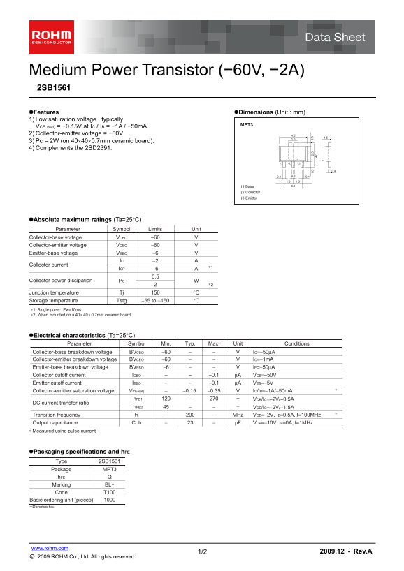
Page 1 Text Content
Medium Power Transistor (−60V, −2A) 2SB1561
Features Dimensions (Unit : mm)
1) Low saturation voltage , typically
VCE (sat) = −0.15V at IC / IB = −1A / −50m A. 2) Collector-emitter voltage = −60V 4.5
3) Pc = 2W (on 40400.7mm ceramic board). 4) Complements the 2SD2391.
1.51.5 (1)Base 3.0
(2)Collector (3)Emitter
Absolute maximum ratings (Ta=25C)
Parameter Symbol Limits Unit Collector-base voltage VCBO −60 Collector-emitter voltage VCEO −60
Emitter-base voltage VEBO −6
IC −2
Collector current
ICP −6
Collector power dissipation PC
Junction temperature Tj °C
Storage temperature Tstg −55 to +150 °C
∗1 Single pulse, Pw=10ms
∗2 When mounted on a 40 40 0.7mm ceramic board.+ 4. 02.
Electrical characteristics (Ta=25C)
Parameter Symbol Min. Typ. Max. Unit Conditions
Collector-base breakdown voltage BVCBO −60 IC=−50μA
Collector-emitter breakdown voltage BVCEO −60 IC=−1m A Emitter-base breakdown voltage BVEBO −6 IE=−50μA
Collector cutoff current ICBO −0.1 μA VCB=−50V
Emitter cutoff current IEBO −0.1 μA VEB=−5V
Collector-emitter saturation voltage VCE(sat) −0.15 −0.35 IC/IB=−1A/−50m A
h FE1 VCE/IC=−2V/−0.5A
DC current transfer ratio
h FE2 VCE/IC=−2V/−1.5A45
Transition frequency f T MHz VCE=−2V, IE=0.5A, f=100MHz Output capacitance Cob p F VCB=−10V, IE=0A, f=1MHz
∗ Measured using pulse current
Packaging specifications and h FE
Type 2SB1561
Package MPT3
Marking BL∗ Code T100
Basic ordering unit (pieces) ∗Denotes h FE
www.rohm.com
1/2 2009.12 - Rev.A
○c 2009 ROHM Co., Ltd. All rights reserved.
Page Summary Contents For ROHM 2SB1561 User Guide and Manual
Manual Details
| Brand | ROHM |
|---|---|
| Pages | 3 |
| File Size | 169.81 KB |
| Published | June 18, 2026 |
Enter the captcha to get the download link:

Frequently Asked Questions
What voltage range is safe for this transistor to operate at?
The maximum collector-emitter voltage (VCEO) and absolute collector-base voltage are rated up to −60V.
Can I use this product in medical or transportation equipment?
No, the products are not designed for systems requiring an extremely high level of reliability; contact a sales representative for special purpose use.
What is the typical power dissipation limit for normal operation?
The collector power dissipation (Pc) is specified as 2W when mounted on a 40x40x0.7mm ceramic board.
What is the guaranteed transition frequency ($f_T$) of the device?
The transition frequency $f_T$ is listed at −200 MHz under specific operating conditions (VCE=−2V, IE=0.5A, f=100MHz).