ROHM 2SB1427 Data Sheet
Summary
2SB1427 PNP power transistor, -20V/-2A. Low Vce(sat) -0.5V max, hFE 390-820, 90MHz fT, 0.5W in MPT3 package. For electronics engineers designing power switching, LED drivers, and amplifier stages requiring compact PNP solutions.
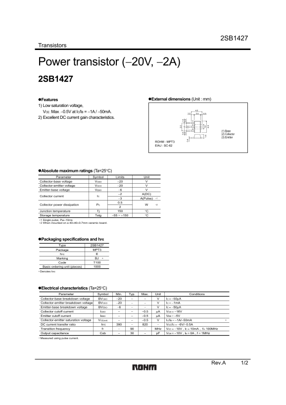
Page 1 Text Content
2SB1427
Transistors
Power transistor (−20V, −2A) 2SB1427
Features External dimensions (Unit : mm)
1) Low saturation voltage,
VCE : Max . −0.5V at IC/IB = −1A / −50m A.
2) Excellent DC current gain characteristics.
(1) Base (2) Collector (3) Emitter
ROHM : MPT3 EIAJ : SC-62
Absolute maximum ratings (Ta=25°C) Parameter Symbol Limits Unit
Collector-base voltage VCBO −20
1. 1. Collector-emitter voltage VCEO −20 0. 0. 0. 0.
Emitter-base voltage VEBO −6
−2 A(DC)
Collector current IC
−3 A(Pulse) ∗1
Collector power dissipation PC ∗2 1.
Junction temperature Tj °C Tstg −55 ~ +150 °CStorage temperature
∗1 Single pulse, Pw=10ms ∗2 When mounted on a 40×40×0.7mm ceramic board.
Packaging specifications and h FE
Type 2SB1427
Package MPT3
Marking BJ Code T100
Basic ordering unit (pieces) Denotes h FE∗
Electrical characteristics (Ta=25°C)
Parameter Symbol Min. Typ. Max. Unit Conditions
Collector-base breakdown voltage BVCBO −20 IC = −50µA Collector-emitter breakdown voltage BVCEO −20 IC = −1m A Emitter-base breakdown voltage BVEBO −6 IE = −50µA Collector cutoff current ICBO −0.5 µA VCB = −16V Emitter cutoff current IEBO −0.5 µA VEB = −5V
Collector-emitter saturation voltage VCE(sat) −0.5 IC/IB = −1A/−50m A
DC current transfer ratio h FE VCE/IC = −6V/−0.5A Transition frequency f T MHz VCE = −10V , IE = 10m A , f= 100MHz Output capacitance Cob p F VCB = −10V , IE = 0A , f = 1MHz
Measured using pulse current.∗
Rev.A 1/2
Page Summary Contents For ROHM 2SB1427 Data Sheet
Manual Details
| Brand | ROHM |
|---|---|
| Pages | 3 |
| File Size | 63.35 KB |
| Published | June 16, 2026 |
Enter the captcha to get the download link:

Frequently Asked Questions
What is the maximum collector current for the 2SB1427 transistor?
The DC collector current (IC) maximum is -2A.
How should I mount the 2SB1427 for the rated power dissipation?
For the rated 0.5W power dissipation (PC), it should be mounted on a 40×40×0.7mm ceramic board.
What is the typical DC current gain (hFE) range for the 2SB1427?
The DC current gain (hFE) ranges from 390 to 820 under VCE/IC = -6V/-0.5A.
What is the maximum collector-emitter saturation voltage?
The maximum collector-emitter saturation voltage (VCE(sat)) is -0.5V at IC/IB = -1A/-50mA.