ROHM 2SB1316 Data Sheet
Summary
Power your electronic devices with this high-performance power transistor, engineered with a robust Darlington connection structure for superior DC current gain. This detailed technical manual provides engineers and circuit designers with comprehensive specifications, covering absolute maximum ratings, critical electrical characteristics graphs, and safe operating area guidelines. Ideal for integrating into general-use equipment like audio/visual gear or office automation systems where reliable, high-efficiency power switching is required.
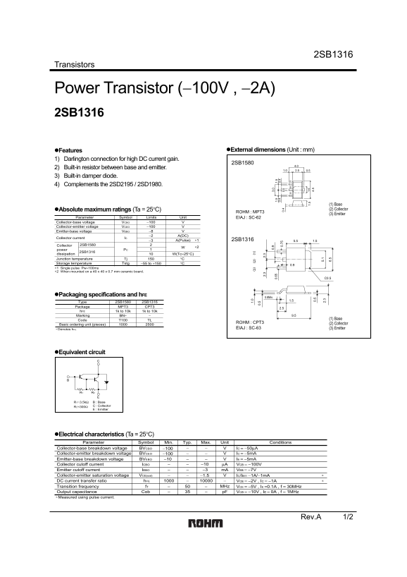
Page 1 Text Content
2SB1316
Transistors
Power Transistor (−100V , −2A) 2SB1316
Features External dimensions (Unit : mm)
1) Darlington connection for high DC current gain.
2SB1580
2) Built-in resistor between base and emitter.
3) Built-in damper diode.
4) Complements the 2SD2195 / 2SD1980.
(1) Base Absolute maximum ratings (Ta = 25°C) (2) Collector
ROHM : MPT3
(3) Emitter
Parameter Symbol Limits Unit EIAJ : SC-62
Collector-base voltage VCBO −100 Collector-emitter voltage VCEO −100 Emitter-base voltage VEBO −8
−2 A(DC)
Collector current IC
−3 ∗1A(Pulse) 2SB1316 1.55.5
Collector 2SB1580
power PC
2SB1316 1.
dissipation W(Tc=25°C) Junction temperature Tj °C 0.
Storage temperature Tstg −55 to +150 °C
∗1 Single pulse Pw=100ms ∗2 When mounted on a 40 x 40 x 0.7 mm ceramic board.
Packaging specifications and h FE
0.8Min.
Type 2SB1580 2SB1316 Package MPT3 CPT3
h FE 1k to 10k 1k to 10k 1.
Marking BN∗ 9.5
Code T100 TL (1) Base
ROHM : CPT3 5. (2) Collector
Basic ordering unit (pieces) 2. 30.
Denotes h FE EIAJ : SC-63 (3) Emitter
Equivalent circuit
R1 3.5kΩ : Base R2 300Ω : Collector : Emitter
Electrical characteristics (Ta = 25°C) Parameter Symbol Min. Typ. Max. Unit Conditions
Collector-base breakdown voltage BVCBO −100 IC = −50µA Collector-emitter breakdown voltage BVCEO −100 IC = −5m A BVEBO −10 IE = −5m AEmitter-base breakdown voltage
Collector cutoff current ICBO −10 µA VCB = −100V Emitter cutoff current IEBO −3 m A VEB = −7V
Collector-emitter saturation voltage VCE(sat) −1.5 IC/IB= −1A/−1m A
DC current transfer ratio h FE ∗VCE = −2V , IC = −1A
f T 50− MHz VCE = −5V , IE =0.1A , f = 30MHz Transition frequency Output capacitance Cob p F VCB = −10V , IE = 0A , f = 1MHz
∗Measured using pulse current.
Rev.A 1/2
Page Summary Contents For ROHM 2SB1316 Data Sheet
Manual Details
| Brand | ROHM |
|---|---|
| Pages | 3 |
| File Size | 125.23 KB |
| Published | June 04, 2026 |
Enter the captcha to get the download link:

Frequently Asked Questions
What is the primary feature of the 2SB1316?
It has a Darlington connection for high DC current gain and includes a built-in resistor between base and emitter.
What are the absolute maximum operating voltage ratings?
The Collector-base voltage (VCBO) and Collector-emitter voltage (VCEO) limits are both -100 V.
Can I use this component in high-stress environments?
The storage temperature range (Tstg) is from -55 to +150 °C.
What are the current transfer ratio ranges for this transistor?
The transistor's hFE rating varies from a minimum of 0.8 to 3A(DC).