Rockwell Automation PowerFlex 700 Internal Dynamic Brake Kits Installation User's Manual
Summary
This comprehensive guide is for installing and integrating PowerFlex 700 Internal Dynamic Brake Kits, essential components for maintaining robust motor braking performance in industrial automation systems. The manual provides detailed technical specifications, wiring diagrams, precise torque values, and installation instructions across various drive frames and module sizes. It is designed for electrical engineers, maintenance technicians, and control system professionals seeking reliable integration of VFD braking accessories into their power control solutions.
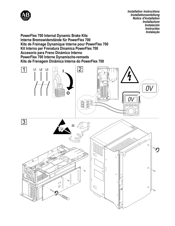
Page 1 Text Content
Installation Instructions Installationsanleitung Notice d'installation
Installazione Instalación Instructies Instalação
Power Flex 700 Internal Dynamic Brake Kits Interne Bremswiderstände für Power Flex 700 Kits de Freinage Dynamique Interne pour Power Flex 700 Kit Interno per Frenatura Dinamica Power Flex 700 Accesorio para Freno Dinámico Interno Power Flex 700 Interne Dynamische-remsets Kits de Frenagem Dinâmica Interna do Power Flex 700 L1 L2 L3
DANGER
Use 75C Wire Only
#10-#14 AWG
Torque to 7 in-lbs
DC– 0V PE U/T1 V/T2 W/T3 R/L1 S/L2 T/L3
DC+ 0V
BR1BR2DC+DC-PE
Page Summary Contents For Rockwell Automation PowerFlex 700 Internal Dynamic Brake Kits Installation User's Manual
Manual Details
| Brand | Rockwell Automation |
|---|---|
| Pages | 4 |
| File Size | 468.16 KB |
| Published | June 05, 2026 |
Enter the captcha to get the download link:

Frequently Asked Questions
What wire type must be used for power connections?
Use only 75C Wire.
What are the appropriate gauge ranges for the wires?
The manual indicates that #10-#14 AWG copper wire is recommended.
Can this kit be installed on different frame sizes?
Yes, it supports Frame 0 (4a), Frame 1 (4b), and Frame 2 (4c).
What are the specified torque values for installation?
One listed torque value is 7 in-lbs, and another section specifies a torque of 1.4 N-M.