RICOH RP131x Series Low Voltage 1A LDO Data Sheet User Manual
Summary
The RP131x Series is a high-efficiency CMOS LDO regulator designed for low voltage applications requiring up to 1A of stable power. Featuring an ultra-low dropout voltage, it supports seamless operation from 1.6V to 6.5V (VIN) with customizable outputs between 0.8V and 5.5V. This manual provides comprehensive technical details, including specifications for the thermal shutdown, inrush current limit, and fold-back protection circuits. Ideal for developers of battery-powered equipment such as hand-held communicators, cameras, and complex electronic systems needing reliable DC/DC conversion stabilization.
Page 1 Text Content
RP131x Series Low Voltage 1A LDO
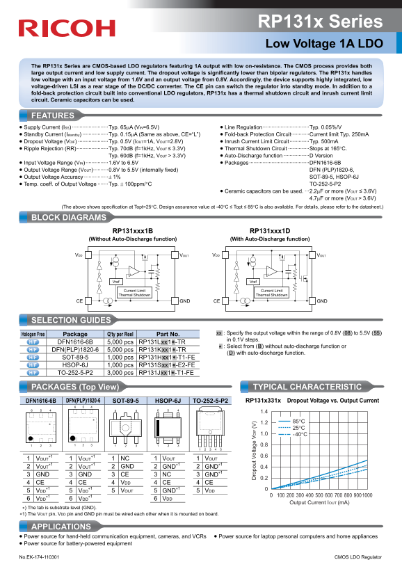
The RP131x Series are CMOS-based LDO regulators featuring 1A output with low on-resistance. The CMOS process provides both large output current and low supply current. The dropout voltage is significantly lower than bipolar regulators. The RP131x handles low voltage with an input voltage from 1.6V and an output voltage from 0.8V. Accordingly, the device supports highly integrated, low voltage-driven LSI as a rear stage of the DC/DC converter. The CE pin can switch the regulator into standby mode. In addition to a fold-back protection circuit built into conventional LDO regulators, RP131x has a thermal shutdown circuit and inrush current limit circuit. Ceramic capacitors can be used.
FEATURES • Supply Current (ISS) ························Typ. 65μA (VIN=6.5V) • Line Regulation·······························Typ. 0.05%/V • Standby Current (Istandby) ·················Typ. 0.15μA (Same as above, CE=“L”) • Fold-back Protection Circuit············Current limit Typ. 250m A • Dropout Voltage (VDIF) ····················Typ. 0.5V (IOUT=1A, VOUT=2.8V) • Inrush Current Limit Circuit ·············Typ. 500m A • Ripple Rejection (RR)·····················Typ. 70d B (f=1k Hz, VOUT ≤ 3.3V) • Thermal Shutdown Circuit ··············Stops at 165°C.
Typ. 60d B (f=1k Hz, VOUT > 3.3V) • Auto-Discharge function ·················D Version
• Input Voltage Range (VIN) ···············1.6V to 6.5V • Packages ········································DFN1616-6B • Output Voltage Range (VOUT)··········0.8V to 5.5V (internally fixed) DFN (PLP)1820-6, • Output Voltage Accuracy ················± 1% SOT-89-5, HSOP-6J • Temp. coeff. of Output Voltage ·······Typ. ± 100ppm/°C TO-252-5-P2
• Ceramic capacitors can be used. ···2.2μF or more (VOUT ≤ 3.6V) 4.7μF or more (VOUT > 3.6V)
(The above shows specification at Topt=25°C. Design assurance value at -40°C ≤ Topt ≤ 85°C is also available. For details, please refer to the datasheet.)
BLOCK DIAGRAMS
RP131xxx1B RP131xxx1D
(Without Auto-Discharge function) (With Auto-Discharge function)
VDD ro lt IF VOUT VDD VOUT
Vref Vref
Current Limit Current Limit Thermal Shutdown Thermal Shutdown
CE GND CE GND
SELECTION GUIDES
.xx. : Specify the output voltage within the range of 0.8V (.08.) to 5.5V (.55.)
Halogen Free Package Q'ty per Reel Part No.
in 0.1V steps.
DFN1616-6B 5,000 pcs RP131L.xx.1.∗ -TR
.∗ : Select from (.B.) without auto-discharge function or
DFN(PLP)1820-6 5,000 pcs RP131K.xx.1.∗ -TR
(.D.) with auto-discharge function.
SOT-89-5 1,000 pcs RP131H.xx.1.∗ -T1-FE HSOP-6J 1,000 pcs RP131S.xx.1.∗ -E2-FE TO-252-5-P2 3,000 pcs RP131J.xx.1.∗ -T1-FE
PACKAGES (Top View) TYPICAL CHARACTERISTIC
DFN1616-6B DFN(PLP)1820-6 SOT-89-5 HSOP-6J TO-252-5-P2 RP131x331x Dropout Voltage vs. Output Current
1 VOUT 1 VOUT 1 NC 1 VOUT VOUT ∗1 ∗1 2 VOUT 2 VOUT 2 GND 2 GND∗1 GND∗1 0.4 3 GND 3 GND 3 CE 3 NC GND∗1
4 CE 4 CE 4 VDD 4 CE CE ∗1 ∗1 5 VDD 5 VDD 5 VOUT 5 GND∗1 VDD ∗1 ∗1 6 VDD 6 VDD 6 VDD
Output Current IOUT (m A)
∗) The tab is substrate level (GND). ∗1) The VOUT pin, VDD pin and GND pin must be wired each other when it is mounted on board.
APPLICATIONS • Power source for hand-held communication equipment, cameras, and VCRs • Power source for laptop personal computers and home appliances • Power source for battery-powered equipment No.EK-174-110301 CMOS LDO Regulator
Page Summary Contents For RICOH RP131x Series Low Voltage 1A LDO Data Sheet User Manual
Manual Details
| Brand | Ricoh |
|---|---|
| Pages | 2 |
| File Size | 256.05 KB |
| Published | June 05, 2026 |
Enter the captcha to get the download link:

Frequently Asked Questions
What protection mechanisms are built into the RP131x regulator?
It includes a fold-back protection circuit, thermal shutdown circuit, and an inrush current limit circuit.
How should I select capacitors when using this device?
Use 2.2μF or more if VOUT ≤ 3.6V, and use 4.7μF or more if VOUT > 3.6V.
Is there a way to minimize the current draw when not in use?
Yes, you can switch it into standby mode by activating the CE pin.