RICOH RP132x Series Low Voltage 1A LDO with Ext. VOUT Adjustable Data Manual User Guide
Summary
This high-performance CMOS LDO regulator provides reliable 1A power output with excellent load regulation and built-in inrush current protection. Available in fixed or externally adjustable versions, it is engineered for demanding portable applications. This manual offers comprehensive technical specifications, selection guides, and application techniques necessary to integrate the unit into communication equipment, cameras, and battery-powered electronics requiring stable voltage supply.
Page 1 Text Content
RP132x Series
Low Voltage 1A LDO with Ext. VOUT Adjustable
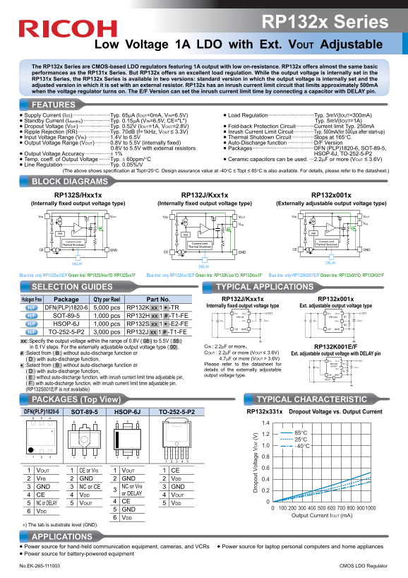
The RP132x Series are CMOS-based LDO regulators featuring 1A output with low on-resistance. RP132x offers almost the same basic performances as the RP131x Series. But RP132x offers an excellent load regulation. While the output voltage is internally set in the RP131x Series, the RP132x Series is available in two versions: standard version in which the output voltage is internally set and the adjusted version in which it is set with an external resistor. RP132x has an inrush current limit circuit that limits approximately 500m A when the voltage regulator turns on. The E/F Version can set the inrush current limit time by connecting a capacitor with DELAY pin.
FEATURES • Supply Current (ISS) ························Typ. 65μA (IOUT=0m A, VIN=6.5V) • Load Regulation······························Typ. 3m V(IOUT=300m A) • Standby Current (Istandby) ·················Typ. 0.15μA (VIN=6.5V, CE="L") Typ. 5m V(IOUT=1A) • Dropout Voltage (VDIF) ····················Typ. 0.52V (IOUT=1A, VOUT=2.8V) • Fold-back Protection Circuit············Current limit Typ. 250m A • Ripple Rejection (RR)·····················Typ. 70d B (f=1k Hz, VOUT ≤ 3.3V) • Inrush Current Limit Circuit ·············Typ. 500m A(for 500μs after start-up) • Input Voltage Range (VIN) ···············1.4V to 6.5V • Thermal Shutdown Circuit ··············Stops at 165°C. • Output Voltage Range (VOUT)··········0.8V to 5.5V (internally fixed) • Auto-Discharge function ·················D/F Version
0.8V to 5.5V with external resistors • Packages ········································DFN (PLP)1820-6, SOT-89-5,
• Output Voltage Accuracy ················± 1% HSOP-6J, TO-252-5-P2 • Temp. coeff. of Output Voltage ·······Typ. ± 60ppm/°C • Ceramic capacitors can be used. ···2.2μF or more (VOUT ≤ 3.6V) • Line Regulation·······························Typ. 0.05%/V
(The above shows specification at Topt=25°C. Design assurance value at -40°C ≤ Topt ≤ 85°C is also available. For details, please refer to the datasheet.)
BLOCK DIAGRAMS
RP132S/Hxx1x RP132J/Kxx1x RP132x001x
(Internally fixed output voltage type) (Internally fixed output voltage type) (Externally adjustable output voltage type)
VDD VOUT VDD VOUT VDD VOUT
VFB VFB
Vref Vref
Current Limit Current Limit
Thermal Shutdown Current Limit Thermal Shutdown Thermal Shutdown
CE GND CE GND
CE GND
ro lt IF
DELAY DELAY
DELAY
Blue line: only RP132Sxx1E/F Green line: RP132S/Hxx1D, RP132Sxx1F Blue line: only RP132Kxx1E/F Green line: RP132K/Jxx1D, RP132Kxx1F Blue line: only RP132K0001E/F Green line: RP132x001D, RP132K001F
SELECTION GUIDES TYPICAL APPLICATIONS
Halogen Free Package Q'ty per Reel Part No. RP132J/Kxx1x RP132x001x
Internally fixed output voltage type Ext. adjustable output voltage type
DFN(PLP)1820-6 5,000 pcs RP132K.xx.1.∗ -TR
VDD VOUT OUT VDD VOUT OUT
SOT-89-5 1,000 pcs RP132H.xx.1.# -T1-FE RP132 RP132J R1
CIN VFB COUT CIN VFB COUT
HSOP-6J 1,000 pcs RP132S.xx.1.∗ -E2-FE R2
CE GND CE GND
TO-252-5-P2 3,000 pcs RP132J.xx.1.# -T1-FE
.xx :Specify the output voltage within the range of 0.8V (.08.) to 5.5V (.55.)
in 0.1V steps. For the externally adjustable output voltage type (.00). CIN : 2.2μF or more、 RP132K001E/F #. :Select from (.B.) without auto-discharge function or COUT : 2.2μF or more (VOUT ≤ 3.6V) Ext. adjustable output voltage with DELAY pin (.D.) with auto-discharge function. 4.7μF or more (VOUT > 3.6V) OUT
VDD VOUT
Please refer to the datasheet for RP132K R1
∗. :Select from (.B.) without auto-discharge function or CIN 001E/F COUT VFB
details of the externally adjustable R2
(.D.) with auto-discharge function,
output voltage type. CE GND
(.E.) without auto-discharge function, with inrush current limit time adjustable pin, DELAY (.F.) with auto-discharge function, with inrush current limit time adjustable pin. (RP132S001E/F is not available)
PACKAGES (Top View) TYPICAL CHARACTERISTIC DFN(PLP)1820-6 SOT-89-5 HSOP-6J TO-252-5-P2 RP132x331x Dropout Voltage vs. Output Current 6 5 4
1 VOUT 1 CE or VFB 1 VOUT 1 CE 2 VFB 2 GND 2 GND 2 VDD 0.4 3 GND 3 NC or CE 3 GND
3 NC or VFB 0.2 4 CE 4 VDD or DELAY 4 VOUT 4 CE
5 NC or DELAY 5 VOUT 5 VDD
5 GND
6 VDD
Output Current IOUT (m A)
6 VDD
∗) The tab is substrate level (GND).
APPLICATIONS • Power source for hand-held communication equipment, cameras, and VCRs • Power source for laptop personal computers and home appliances • Power source for battery-powered equipment No.EK-265-111003 CMOS LDO Regulator
Page Summary Contents For RICOH RP132x Series Low Voltage 1A LDO with Ext. VOUT Adjustable Data Manual User Guide
Manual Details
| Brand | Ricoh |
|---|---|
| Pages | 2 |
| File Size | 367.52 KB |
| Published | May 29, 2026 |
Enter the captcha to get the download link:

Frequently Asked Questions
What should I use as input capacitance for this regulator?
Use ceramic capacitors of 2.2μF or more if your output voltage (VOUT) is less than or equal to 3.6V.
Does the regulator protect against sudden current spikes upon startup?
Yes, it has an inrush current limit circuit that limits approximately 500mA for about 500μs when the device powers on.
How good is its performance regarding load variation?
It offers excellent load regulation, typically only 3mV at a constant output current of 300mA.