RICOH RP111x Series Good Load Transient Response Low Voltage 500mA LDO Data Sheet User Manual
Summary
This high-performance RP111x series LDO regulator provides efficient power management for demanding electronic applications. Capable of delivering 500mA output current with a very low dropout voltage, it features exceptional load transient response and minimal standby consumption (down to 0.1μA). The manual details its enhanced accuracy, ripple rejection (75dB), and integrated protections including fold-back and thermal shutdown. It is the ideal power solution for battery-powered devices, hand-held communication equipment, cameras, and digital home appliances requiring reliable low-voltage power from an input range of 1.4V to 5.25V.
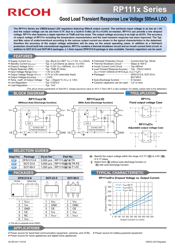
Page 1 Text Content
RP111x Series
Good Load Transient Response Low Voltage 500m A LDO
The RP111x Series are CMOS-based LDO regulators featuring 500m A output current. The minimum input voltage is as low as 1.4V and the output voltage can be set from 0.7V. Due to a built-in 0.46Ω (at VOUT=2.8V) on-resistor, RP111x can provide a low dropout voltage. RP111x also features a ripple rejection at 75d B and low noise. The output voltage accuracy is as high as ±0.8%. The accuracy of output voltage of RP111x including the temperature characteristics and the load transient response has been improved. The Typ. and Max value of under/overshoot according to the various output current are shown in the typical characteristics in the datasheet, therefore the accuracy of the output voltage estimation will be easy on the actual operating cases. In addition to a fold-back protection circuit built into conventional regulators, RP111x contains a thermal shutdown circuit and an inrush current limit circuit. In addition to SOT-23-5 and SOT-89-5 packages, a 1.2mm square DFN1212-6 package is also available. Ceramic capacitors can be used.
FEATURES • Supply Current (ISS) ····················· Typ. 80μA (VIN=SET VOUT+1.0V, IOUT=0m A) • Fold-back Protection Circuit ···········Current limit Typ. 50m A • Standby Current (Istandby) ·············· Typ. 0.1μA (Same as above, VCE=0V) • Thermal Shutdown Circuit ··············Stops at 165°C • Dropout Voltage (VDIF) ················· Typ. 0.23V (IOUT=500m A, VOUT=2.8V) • Inrush Current Limit Circuit ···········Typ.400m A • Ripple Rejection (RR)·················· Typ. 75d B (f=1k Hz) • Load Transient Response Accuracy·····Typ. -75m V/+45m V • Input Voltage Range (VIN) ············ 1.4V to 5.25V (IOUT=1m A⇔250m A (tr=tf=0.5μs), COUT=1μF) • Output Voltage Range (VOUT)······· 0.7V to 3.6V (internally fixed) • Packages········································DFN1212-6, SOT-23-5, • Output Voltage Accuracy ············· ± 0.8% SOT-89-5 • Temp. coeff. of Output Voltage ···· Typ. ± 30ppm/°C (VOUT ≥ 1.8V) • Auto-Discharge function ·················D Version • Line Regulation···························· Typ. 0.02%/V • Ceramic capacitors can be used. ···1μF or more • Load Regulation ·························· Typ. 1m V
(The above shows specification at Topt=25°C. Design assurance value at -40°C ≤ Topt ≤ 85°C is also available. For details, please refer to the datasheet.)
BLOCK DIAGRAM TYPICAL APPLICATIONS
RP111xxx1B RP111xxx1D RP111x
(Without Auto-Discharge function) (With Auto-Discharge function) Fixed output voltage Case
ro po ut ol ta ge IF (m
VDD VOUT OUTIN
RP111x
VDD VOUT VDD VOUT
CIN VFB COUT
VFB VFB CE GND
Vref Vref
RP111x07x
Current Limit Current Limit Adjustable output voltage Case Thermal Shutdown Thermal Shutdown
CE GND CE GND VDD VOUT OUTIN
RP111x
CIN VFB COUT
CE GND
SELECTION GUIDES
Part No. .xx. : Specify the output voltage within the range of 0.7V (.07.) to 3.6V (.36.)
Halogen Free Package Q'ty per Reel
in 0.1V steps.
DFN1212-6 5,000 pcs RP111L.xx.1.∗ -TR
.∗ : Select from (.B.) without auto-discharge function or
SOT-23-5 3,000 pcs RP111N.xx.1.∗ -TR-FE
(.D.) with auto-discharge function.
SOT-89-5 1,000 pcs RP111H.xx.1.∗ -T1-FE
PACKAGES TYPICAL CHARACTERISTIC
DFN1212-6 SOT-23-5 SOT-89-5 RP111x281x Dropout Voltage vs. Output Current
Top View Bottom View 5 4
Topt=85°C Topt=25°C Topt=-40°C
1 VOUT 1 VDD 1 VFB 2 VFB 2 GND 2 GND 3 GND 3 CE 3 CE 4 CE 4 VFB 4 VDD 5 NC 5 VOUT 5 VOUT 6 VDD Output Current IOUT(m A) ∗) The tab is substrate level (GND)
APPLICATIONS • Power source for hand-held communication equipment, cameras, and VCRs • Power source for battery-powered equipment • Power source for home appliances and digital home appliances No.EK-241-110316 CMOS LDO Regulator
Page Summary Contents For RICOH RP111x Series Good Load Transient Response Low Voltage 500mA LDO Data Sheet User Manual
Manual Details
| Brand | Ricoh |
|---|---|
| Pages | 2 |
| File Size | 386.70 KB |
| Published | June 04, 2026 |
Enter the captcha to get the download link:

Frequently Asked Questions
What are the minimum and maximum operating voltages for this LDO regulator?
The input voltage range (VIN) is 1.4V to 5.25V, and the output can be set from 0.7V to 3.6V.
What happens if the device overheats or experiences an excessive inrush current?
It includes a thermal shutdown circuit that stops operation at 165°C, and an integrated inrush current limit circuit (Typ. 400mA).
Does this regulator have built-in protection features?
Yes, it includes fold-back protection, thermal shutdown, and an inrush current limit circuit, along with load regulation.