Page 1
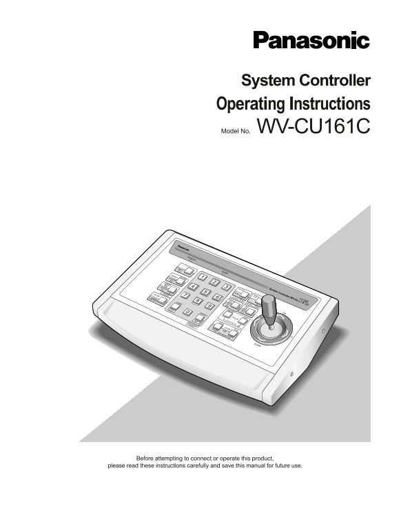
System Controller Operating Instructions Model No. WV-CU161C OPERATE SHIFT ALARM RESET SUSPEND ALARM CAMERASETUP SETUP AUTO System Controller WV-CU C SLOW PROGRAM B/W PATROLPLAY FUNCTION CAMERA PATROL...
Page 2
ENGLISH VERSION Caution: Before attempting to connect or operate this product, please read the label on the bottom. For U.S.A NOTE: This equipment has been tested and found to comply with the limits f...
Page 3
IMPORTANT SAFETY INSTRUCTIONS 1) Read these instructions. 2) Keep these instructions. 3) Heed all warnings. 4) Follow all instructions. 5) Do not use this apparatus near water. 6) Clean only with dry ...
Page 4
CONTENTS IMPORTANT SAFETY INSTRUCTIONS ........................................................................................................................................ FEATURES ..................
Page 5
PREFACE The WV-CU161C System Controller is designed for one-to-one use with a Combination Camera or WV-RC100/WV-RC150 Receiver that is provided with camera control functions. You can operate the pan/t...
Page 6
PRECAUTIONS Refer all work related to the installation of this Do not expose the appliance to water or moisture. product to qualified service personnel or system Do not try to operate it in wet areas....
Page 7
MAJOR OPERATING CONTROLS AND THEIR FUNCTIONS ■Front View System Controller WV-CU C OPERATE ALARM AUTO PATROL !3 PLAY SHIFT B/W PATROL STOP PATROL LEARN UP ALARM RESET WIPER DEF SUSPEND AUX1 AUX2 CAMER...
Page 8
Wiper/Auxiliary 1 Button (WIPER/AUX1) !2 Home/Escape Button (HOME/ESC) Pressing this button will turn the housing wipers on or HOME: This button is used to return a specific camera off for cameras pro...
Page 9
■Rear View RS485ALARM DATA VIDEO CAMERA POWER ALARM IN OUT IN ALARM OUT RECOVER IN RT TERM LINE RESET OUT ABABG ON COAX ON OFF OFF RS485 ALARM IN SIGNAL GND rty !0 !1eq Alarm Switch Video Output Conne...
Page 10
INSTALLATION CAUTION Installation should be performed by qualified service personnel or system installers according to the following instruc- tions. Disconnect the power cord from the service outlet b...
Page 11
CONNECTION & SETTING ■System Connection Basic Connection The WV-CU161C can be connected with a camera, a Time Lapse VCR and a video monitor as in the typical system configura- tion shown below. Co...
Page 12
Connecting more Cameras A bi-directional video switcher purchased separately can be installed when connecting more than one camera. Video signal reception, camera control and alarm input reception are...
Page 13
Connecting with a Distant Camera Site Using two Network Interface Units, that is a Transmitter and a Receiver, will help to extend the distance between the camera and control sites. An RS-485 is used ...
Page 14
■Connection with a Time Lapse VCR Alarm in/out and recover-reset in/out are connected between the time lapse VCR and the rear of the controller. Note: Use a relay as shown below when connecting an ind...
Page 15
■RS-485 Connection Control data is transmitted and received between the con- troller and other peripherals. Use a shielded cable of data communication grade, consisting of two twisted pairs suit- able...
Page 16
■Switch Setting There are four switches on the rear of the controller for specifying the terminal definition and data communication conditions. A signal form selection switch (SW1) and a character dis...
Page 17
Internal Switch Setting Caution: The internal switch setting should be performed by qualified service personnel or system installers. Unplug the controller power cord from the electric outlet before s...
Page 18
3. Set the SW100 to the desired position. The default set- ting is NOR. NOR: White letters are displayed with a black border. REV: Black letters are displayed with a white border. SW100 NOR REV 4. Pla...
Page 19
SETUP MENU The SETUP MENU has four main submenus: Alarm Setup, System Setup, Preset Data Load and Communication. All of these main menus are further divided into submenus. SETUP MENU ALARM SETUP ........
Page 20
Closing Setup Menu Note: The display time differs depending on the Alarm Press the PRESET/SET/PROGRAM PRESET button for 2 Output Setting. seconds or more while the SHIFT indicator is lit. The SETUP in...
Page 21
Alarm Buzzer Setting Alarm Terminal This item lets you select whether or not to sound the alarm The menu below appears when the ALARM switch on the buzzer when an alarm is activated. rear of the contr...
Page 22
■System Setup ■Preset Data Loading 1. Display the WV-CU161C SETUP MENU. The data settings preset to the camera are downloaded to 2. Select SYSTEM SETUP by moving the joystick up or the controller. A s...
Page 23
6. The text line LOADING blinks on the right while down- Uploading loading. 1. Display the PRESET DATA LOAD menu. The bar graph changing from ■ to P displays the down- 2. Select a camera number betwee...
Page 24
Check that the right unit address is selected for the 6. Repeat step 5 to complete the data title. A title of up to combination camera when using the RS-485 mode. The 12 characters can be selected. ca...
Page 25
■Communication Setup Parity Check This item lets you set the parity check mode for RS-485 Note: The COMMUNICATION menu appears when the communication. DATA switch is set to RS-485. 1. Display the COMM...
Page 26
OPERATING PROCEDURES CAMERA CONTROL FUNCTIONS Lens Control Camera control functions are operable. A motorized lens can be controlled. It is necessary to set up the camera before using the cam- 1. Pres...
Page 27
Operation of Combination Camera Auto Pan The combination camera starts a specific panning mode It is necessary to set up the combination camera before preset beforehand. operating it. For further setu...
Page 28
Patrol Play The combination camera reproduces a series of pan/tilt movements and lens controls that have been preset before- hand in Patrol Learning. See page 33 to program the camera patrol learning ...
Page 29
Combination Camera Shortcuts The combination camera is controlled using the hundred shortcuts shown in the table. While the SHIFT indicator is lit, type a number using the numeric buttons, and then pr...
Page 30
Camera Housing Control External Device Control Wiper Control Auxiliary Control The camera housing provided with the wiper is controlled. An auxiliary device connected to the Receiver or a camera is co...
Page 31
Notes: ALARM CONTROL FUNCTIONS Alarm display On/Off and Buzzer On/Off mode can be When the WV-CU161C receives an alarm signal from a selected. (See page 20 and 21.) camera site, an alarm is activated....
Page 32
Notes: CAMERA SETUP To display the special menu, move the cursor to [SPE- The camera setup operations are available using the WV- CIAL] on the setup menu and simultaneously hold down CU161C controller...
Page 33
Camera Patrol Learning Camera Preset Position There are two ways of setting the camera patrol learning. There are two ways of presetting camera positions. One is One is to use the setup menu and the o...
Page 34
ALL RESET The WV-CU161C System Controller can be reset to the 3. Resetting has been completed when all LEDs light up default settings as follows: for a few seconds and then go off (except for the Oper...
Page 35
SPECIFICATIONS Power Source: 120 V AC, 60 Hz Power Consumption: 6 W Camera Input: Composite Video Signal: 1 V[p-p]/75 Ω Alarm Input: No-voltage contact Alarm Recover Input: No-voltage contact Video Ou...
Page 36
Panasonic Security and Digital Imaging Company Panasonic Canada Inc. 5770 Ambler Drive, Mississauga, A Division of Matsushita Electric Corporation of America Ontario, L4W 2T3 Canada (905)624-5010 Exec...