Page 1
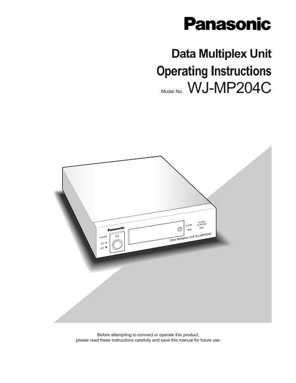
Data Multiplex Unit Operating Instructions Model No. WJ-MP204C ALARM ALARM SUSPEND POWER Data Multiplex Unit WJ-MP204C Before attempting to connect or operate this product, please read these instructi...
Page 2
ENGLISH VERSION We declare under our sole responsibility that the product to which Wij verklaren als enige aansprakelijke, dat het product waarop deze this declaration relates is in conformity with th...
Page 3
IMPORTANT SAFETY INSTRUCTIONS 1) Read these instructions. 2) Keep these instructions. 3) Heed all warnings. 4) Follow all instructions. 5) Do not use this apparatus near water. 6) Clean only with dry ...
Page 4
CONTENTS IMPORTANT SAFETY INSTRUCTIONS ........................................................................................................................................ PREFACE ...................
Page 5
PREFACE The Data Multiplex Unit WJ-MP204C is designed for instal- The monitor and system controller can be located distant lation in a surveillance system, offering system flexibility from the camera ...
Page 6
PRECAUTIONS Refer all work related to the installation of this Do not expose the appliance to water or moisture, product to qualified service personnel or system nor try to operate it in wet areas. in...
Page 7
MAJOR OPERATING CONTROLS AND THEIR FUNCTIONS ■Front View ALARMUNIT POWER ALARM RESET SUSPEND SET UP ALARM SUSPEND ESCSET Data Multiplex Unit WJ-MP204C Power switch and power Indicator (POWER ON OFF) S...
Page 8
■Rear View IN IN IN ALARM / REMOTE RT ABABG SIGNAL GND OUT OUT OUT4 CAMERA VS/VDSPOT RS485 DATA MODE @1 Camera Input Connector 1-4 (CAMERA IN 1 2 3 4) @6 VS/VD Output Connector (VS/VD OUT) These conne...
Page 9
INSTALLATION Warning! Only qualified service personnel or system installers should make all rack mountings, connections or internal settings. If adjustments are required, please refer to the Service M...
Page 10
CONNECTION & SETTING Shown below are some system connection examples using Data Multiplex unit with peripheral devices in PS •Data (Panasonic Security Data) or the Camera Communication Protocols. ...
Page 11
ulti-unit C onnection (P •D ata) axim um of four units can b e connected in a d aisy fashion, from T O T to S T IN and so on, and finally from T to the m onitor. 5 ch 13 ch 8 ch 16 ch 1 ch 9 ch 6 ch 1...
Page 12
●Video Multiplexer Connection (PS •Data) To connect with ordinary cameras that do not have camera control functions, a Video Multiplexer is installed with the WJ- MP204C units at the camera site. 4 ch...
Page 13
●Digital Disk Recorder Connection (PS •Data) To connect with ordinary cameras that do not have camera control functions, a Digital Disk Recorder is installed with the WJ- MP204C units at the camera si...
Page 14
●Matrix Switcher Connection (Camera Communication) The WJ-SX350 and WV-CU360C are typically combined with the WJ-MP204C when using the Camera Communication Protocol. Ordinary cameras are connected dir...
Page 15
●DIP Switch Setting A 6-bit DIP switch mounted on the rear panel specifies communication mode and sync setup. The default position is marked with an asterisk * in the table below. Bit 1 specifies the ...
Page 16
PS •Data Address Assignment UNIT Switch Position Set the Do not Unit address number in given to WJ-MP204C Setup reserved Camera Communication Protocol As shown in the table, the UNIT switch determines...
Page 17
Alarm input Available when TERMINAL is set to ALARM and TERM. ALARM is set to ON in the setup, and the internal connector remains in the default position (CN703, ALM IN): Pin #6 accepts CH 1 alarm inp...
Page 18
Basic Connection Data Multiplex Unit System Controller WJ-MP204C WV-CU360C DATA DATA Termination: Termination: ON ON RS-485 Cable Daisy Connection Video Multiplexer Data Multiplex Unit System Controll...
Page 19
SETUP PROCEDURES ■Prior to setup WJ-MP204C SETUP MENUX.XX ●Confirmation COMMUNICATION SYSTEM 1. Connections and switch settings are complete. 2. Switch on the power of the connected system devices inc...
Page 20
●Setup menus There are two setup menu groups depending on the communication protocol used in the system, menus for PS •Data and for the Camera Communication Protocol. MODE DIP switch # 3 on the rear o...
Page 21
•Data DATA BIT ■Setup Menus for PS 1. Move the cursor to DATA BIT, then specify a bit length ●Communication setup (PS •Data) with the [–] or [+] button. The default setting is 8. Communication paramet...
Page 22
Alarm mode setup 1CH: Camera input 1 will be displayed when the respective alarm operates. 1. Move the cursor to ALARM MODE to select ON or OFF 2CH: Camera input 2 will be displayed. with the [–] or [...
Page 23
Cable compensation/VD2 sync/data setup 3. Move the cursor to VD2. Select a parameter with the [–] or [+] button. The default setting is ON. The COMP/VD2/DATA menu is displayed when you select it The V...
Page 24
Camera Configuration 1. Move the cursor to TERMINAL. Select ALARM or REMOTE with the [–] or [+] button, then press SET. The The CAMERA CONFIG menu is displayed when you select default setting is ALARM...
Page 25
CAM ADDRESS WAIT TIME Camera addresses are assigned to each of the unit's cam- The unit will retransmit data when there is no response dur- era input. ing the specified wait time. 1. Move the cursor t...
Page 26
The ALARM MODE sub menu appears. 6. Move the cursor to ALARM DATA. Select an output time with the [–] or [+] button. The default setting is AUTO2. The unit notifies the connected System Controller (mu...
Page 27
2. Move the cursor to COMP. Select a parameter with the Daisy Mode [–] or [+] button. The default setting is S. This setup lets the unit know whether the data communica- The longer a coaxial cable is ...
Page 28
OPERATION Camera selection and alarm operations are made on the ■Alarm Operation front panel of the unit or WV-CU360C System Controller. ●Alarm Input ■Camera Selection An alarm arises in the following...
Page 29
●Alarm Reset Alarms are reset according to the reset mode (EXT, auto (1S-5M) or OFF) selected in the ALARM OUTPUT setup. Manual resetting Pressing the RESET button on the unit resets the activated ala...
Page 30
SPECIFICATIONS Power Source : 220 - 240 V AC 50 Hz Power Consumption : 7 W Camera Input : 1 V[p-p]/75 Ω x 4 Spot Input : 1 V[p-p]/75 Ω x 1 VS/VD Input : VS (1 V[p-p]/75 Ω), or VD (4 V[p-p]/75 Ω) x1 Ca...
Page 31
STANDARD ACCESSORIES Switch Protector ....................................................................... 1 pc. ALL RESET The Data Multiplex Unit WJ-MP204C can be reset to the default settings as ...
Page 32
Matsushita Electric Industrial Co., Ltd. Central P.O. Box 288, Osaka 530-91, Japan N1001-0 V8QA5878AN Printed in Japan © Matsushita Communication Industrial Co., Ltd. All rights reserved.