Page 1
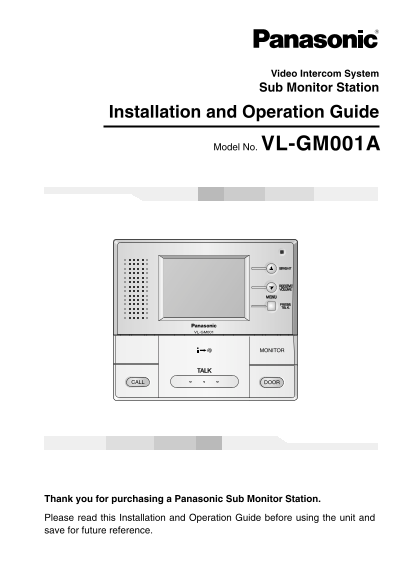
Video Intercom System Sub Monitor Station Installation and Operation Guide Model No. VL-GM001A Thank you for purchasing a Panasonic Sub Monitor Station. Please read this Installation and Operation Gui...
Page 2
Important Information Important Information FCC and Other Information Important safety instructions Additional safety information For best performance Introduction and Installation Included items........
Page 3
Important Information CAUTION RISK OF ELECTRIC SHOCK DO NOT OPEN The lightning flash with arrow The exclamation point within a head within a triangle is triangle is intended to tell the intended to te...
Page 4
Important Information Additional safety information 1. Use only the power source marked on the unit. If you are not sure of the type of power supplied to your home, consult your dealer or local power ...
Page 5
Important Information For best performance If a power failure occurs, the unit will not function. Do not place any object within 20 cm (8 inches) of the sub monitor station. This may cause communicati...
Page 6
Introduction and Installation Included items No. Item Quantity Notes Sub Monitor station Wood screws For the sub monitor station. 4 mm x 35 mm (3/16″ x 13/8″) AC adaptor Enclosed in the AC adaptor cas...
Page 7
Introduction and Installation Location of controls Front view Display (3.5-inch color LCD screen) Microphone • Speak into the microphone when talking to a visitor. SELECT (�) button / BRIGHT button SE...
Page 8
Introduction and Installation Before installation To avoid malfunction or communication disturbance, do not install the sub monitor station in the following locations: Places where vibration or any ot...
Page 9
Introduction and Installation Wiring schematic diagram All monitor stations and sub monitor stations should be connected by daisy chain wiring method. The connection of 2nd sub monitor station (the la...
Page 10
Introduction and Installation Installing the sub monitor station Remove the sub monitor station from the box, and then remove the padding material from between the front case and the bottom case. The ...
Page 11
Introduction and Installation Install the bottom case to a wall using the wood screws (4 mm x 35 mm, 3/16″ x 13/8″). Before drilling, see page 8 for installation location. <Installation size>
Page 12
Introduction and Installation Attach the power cable to the terminal. See page 16 for details on how to attach the power cable. If you want to use your own power cable, see page 9 for the type and dis...
Page 13
Introduction and Installation Remove the sheet covering the connector. Next, after Connector screw installing the terminal cover in the bottom case, attach the connector by tightening the connector sc...
Page 14
Introduction and Installation Take out the AC adaptor and the DC terminal from the case. Push the arrow mark on the front case, then release from the rear case. Take out the cardboard and wood screws....
Page 15
Introduction and Installation To attach the AC adaptor and the DC terminal to a wall By placing the AC adaptor and the DC terminal in the case and mounting the case to the wall, you can protect the AC...
Page 16
Introduction and Installation Note: • To open the case again, push the bottom of the front case, then release from the rear case. To attach the power cable Sub Monitor station DC terminal Button Butto...
Page 17
Cleaning Clean the unit with a soft, dry cloth when cleaning. For excessive dirt, wipe the unit with a slightly damp cloth. Important information: Do not use anything containing alcohol, polish powder...
Page 18
General Information Technical data about this product Sub Monitor station Power supply: 24 V DC Current consumption: Standby: Approximately 38 m A At operation: Approximately 210 m A Dimensions: Appro...
Page 20
For your future reference Date of purchase Serial number (found on the rear of the unit) Dealer’s name and address Dealer’s telephone number Attach your sales receipt here. Panasonic Consumer Electron...