Page 1
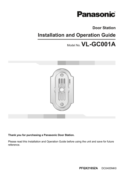
VL-GC001A.book Page 1 Monday, February 28, 2005 12:08 PM Door Station Installation and Operation Guide Model No. VL-GC001A Thank you for purchasing a Panasonic Door Station. Please read this Installat...
Page 2
VL-GC001A.book Page 2 Monday, February 28, 2005 12:08 PM Table of Contents Important Information Important safety instructions . . . . . . . . . . . . . . . . . . . . . . . . . . . . . . . . . . . . ....
Page 3
VL-GC001A.book Page 3 Monday, February 28, 2005 12:08 PM Important Information CAUTION RISK OF ELECTRIC SHOCK DO NOT OPEN The lightning flash with arrow The exclamation point within a head within a tr...
Page 4
VL-GC001A.book Page 4 Monday, February 28, 2005 12:08 PM Important Information Additional safety information 1. Use only the power source marked on the unit. If you are not sure of the type of power s...
Page 5
VL-GC001A.book Page 5 Monday, February 28, 2005 12:08 PM Introduction and Installation Included items No. Item Quantity Notes Door station Mounting bracket Attached to rear of the door station. Wood s...
Page 6
VL-GC001A.book Page 6 Monday, February 28, 2005 12:08 PM Introduction and Installation Location of controls Front view Rear view Camera LWhen a visitor presses the Call Button, the camera will turn on...
Page 7
VL-GC001A.book Page 7 Monday, February 28, 2005 12:08 PM Introduction and Installation Before installation To avoid malfunction or communication disturbances, do not install the door station in the fo...
Page 8
VL-GC001A.book Page 8 Monday, February 28, 2005 12:08 PM Introduction and Installation Note: LThe measurements and angles are for reference purposes and may vary depending on the environment. If a str...
Page 9
VL-GC001A.book Page 9 Monday, February 28, 2005 12:08 PM Introduction and Installation Installing the door station Make sure to install the door station on a flat, vertical wall. Important information...
Page 10
VL-GC001A.book Page 10 Monday, February 28, 2005 12:08 PM Introduction and Installation Attach the mounting bracket to the wall using the wood screws (3.8 mm x 20 mm, 1/8'' x 13/16''). LBefore drillin...
Page 11
VL-GC001A.book Page 11 Monday, February 28, 2005 12:08 PM Introduction and Installation If you want to connect the wires without them going through a hole in the wall behind the mounting bracket, conn...
Page 12
VL-GC001A.book Page 12 Monday, February 28, 2005 12:08 PM Introduction and Installation Insert the hex-head screw using the longer end of the allen wrench. Hex-head screw Allen wrench Attach the bolt ...
Page 13
VL-GC001A.book Page 13 Monday, February 28, 2005 12:08 PM Cleaning Clean the unit with a soft, dry cloth when cleaning. For excessive dirt, wipe the unit with a slightly damp cloth. Important informat...
Page 14
VL-GC001A.book Page 14 Monday, February 28, 2005 12:08 PM General Information Technical data about this product Power supply*1: Standby: Approximately 5 V DC (2 m A) At operation: Approximately 20 V D...
Page 15
VL-GC001A.book Page 15 Monday, February 28, 2005 12:08 PM General Information FCC and Other Information This device complies with Part 15 of the FCC Rules. Operation is subject to the following two co...
Page 16
VL-GC001A.book Page 16 Monday, February 28, 2005 12:08 PM For your future reference Date of purchase Serial number (found on the rear of the unit) Dealer’s name and address Dealer’s telephone number A...