Page 1
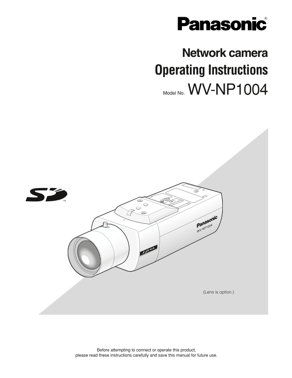
Network camera Operating Instructions Model No. WV-NP1004 PUSH TO LOCK/EJECT WV-NP1004 (Lens is option.) Before attempting to connect or operate this product, please read these instructions carefully ...
Page 2
For Canada CAUTION This Class A digital apparatus complies with Canadian ICES-003. RISK OF ELECTRIC SHOCK DO NOT OPEN For U.S.A NOTE: This equipment has been tested and found to com- CAUTION: TO REDUC...
Page 3
Important Safety Instructions 1) Read these instructions. 2) Keep these instructions. 3) Heed all warnings. 4) Follow all instructions. 5) Do not use this apparatus near water. 6) Clean only with dry ...
Page 4
Limitation of Liability THIS PUBLICATION IS PROVIDED "AS IS" WITHOUT WAR- THIS PUBLICATION COULD INCLUDE TECHNICAL INAC- RANTY OF ANY KIND, EITHER EXPRESS OR IMPLIED, CURACIES OR TYPOGRAPHIC...
Page 5
CONTENTS Important Safety Instructions ............................................................................................................................................. Limitation of Liabi...
Page 6
Preface The network camera WV-NP1004 designed to operate using a PC on a network (10BASE-T/100BASE-TX) and equipped with the traditional analog video output connector (BNC). By connecting to a network...
Page 7
About these operating instructions There are 2 sets of operating instructions for the WV-NP1004 as follows. Operating Instructions (book, these operating instructions) Network Operating Instructions (...
Page 8
Network Security As you will use this product connected to a network, your attention is called to the following security risks. 1. Leakage or theft of information through this product 2. Use of this p...
Page 9
When using an unformatted SD memory card, format it Do not strike or shake, as this may damage the appli- using this camera. ance. Recorded data on the SD memory card will be deleted It may cause a ma...
Page 10
Major Operating Controls and Their Functions Tripod mount base Microphone Fixing screw for transportation * Remove the fixing screw before connecting the power cable. Cover for the operation buttons A...
Page 11
Lens Mounting Mount the lens by rotating it clockwise slowly. Then, connect the lens cable to the ALC lens connector of the camera. ALC lens connector PUSH TO LOCK/EJECT CS-mount lens (optional) CS-mo...
Page 12
How to use a varifocal lens Before adjusting the varifocal lens, reset the flange-back length position to the default position for the CS-mount (by simultane- ously pressing the [LEFT] and [RIGHT] but...
Page 13
Installations/Connections Before start the installation/connection, prepare the required devices and cables. Before starting the connection, turn the power of the devices including the camera and the ...
Page 14
Important: Step 6 Safety wire differs depending on the model and installa- Connect an external device to the EXT I/O connector. tion height of camera mounting bracket (option). When connecting an exte...
Page 15
[Connection example] When connecting with a PC directly AC24V IN VIDEO OUT 1-L POWER SD CARD GND DAY/NIGHT IN AUX OUT LINK ALARM OUT ALARM IN 10BASE-T/ 100BASE-TX LAN cable (category 5, cross) <Req...
Page 16
Insert/Remove SD Memory Card How to insert a SD memory card Important: Before inserting a SD memory card, make sure that the power of the camera is turned off. q Loosen the screw of the w Detach the S...
Page 17
Adjust the Flange-Back Length Before adjusting the flange-back length, adjust the lens first. (→ page 11) Use the operation buttons on the camera (→ page 10) to adjust the flange-back length. The flan...
Page 18
Configure the Settings Using the Operation Buttons on the Camera Each setup item on the [Camera] tab of the "Camera setup" page can be configured using the operation buttons on the cam- era....
Page 19
Basic operation The following are descriptions of how to configure each setup item on the [Camera] tab using the operation buttons on the camera. Note: The illustrations below are the examples of the ...
Page 20
Camera setup page chart <Top page> <CAMERA SETUP page> MODEL WV-NP1004 **CAMERA SETUP** 1/2 **CAMERA SETUP** 2/2 CAMERA CAMERA ID OFF STABILIZER OFF BACK-FOCUS ALC/ELC ALC SPECIAL SHUTTER ...
Page 21
Configure the Network Settings Install the software Before installing the software, read the readme file on the Viewer Software "Network Camera View2" provided CD-ROM first. It is necessary ...
Page 22
Troubleshooting Before asking for repairs, check the symptoms with the following table. Contact your dealer if a problem cannot be solved even after checking and trying the solution or if the problem ...
Page 23
Specifications General specifications Power source AC 24 V 60 Hz Power consumption Approx. 9.5 W Ambient temperature –10 °C - +50 °C Ambient humidity 90 % or less Controller interface Coaxial multiple...
Page 24
S/N 50 d B or more (AGC OFF) Minimum illumination 1.0 lx (color mode), 0.06 lx (BW mode) [Lens F1.4, AGC ON (HIGH), full scanning mode (shut- ter speed 1/30)/partial scanning mode (electronic shutter ...
Page 25
Standard Accessories CD-ROM* ...................................................................... 1 pc. Operating Instructions (English version) ...................... 1 pc. ALC lens connector cap ....
Page 28
Panasonic System Solutions Company, Panasonic Canada Inc. Unit Company of Panasonic Corporation of North America 5770 Ambler Drive,Mississauga, Ontario, L4W 2T3 Canada (905)624-5010 Security Systems h...