Panasonic WVCF224EX User's Manual
Summary
The WV-CF224EX is a high-quality 1/4-inch CCD color camera designed for reliable video surveillance systems. This comprehensive manual provides security installers and technical professionals with essential guidelines covering system installation, wiring standards, power requirements, and advanced operation of all controls (focus, zoom, pan/tilt). It ensures proper setup and safe maintenance for professional-grade monitoring solutions.
Page 1 Text Content
10. Never face the camera towards the sun. 12. Use a monitor whose resolution is at least Do not aim the camera at bright objects. equal to that of the camera. Whether the camera is in use or not, never aim it at the sun or other extremely bright objects. Otherwise, blooming or smear may be caused.
Color CCTV Camera
11. Do not operate the camera beyond its specifications.
Operating Instructions
Use the camera under conditions where temperature is between –10 °C to +50 °C {14 °F to 122 °F}, and humidity is below %. The input power source is 24 V AC or 12 V DC.
Model No.WV-CF224EX
Before attempting to connect or operate this product,
please read these instructions carefully and save this manual for future use. The model numbers in these Operating Instructions are given without suffix.
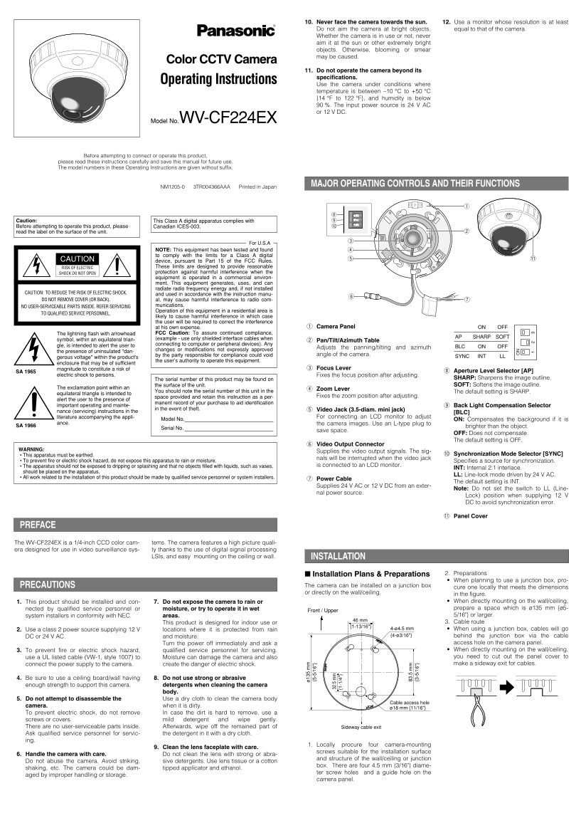
MAJOR OPERATING CONTROLS AND THEIR FUNCTIONS
NM1205-0 3TR004366AAA Printed in Japan
Caution: This Class A digital apparatus complies with
Before attempting to operate this product, please Canadian ICES-003. !0
read the label on the surface of the unit.
For U.S.A
NOTE: This equipment has been tested and found to comply with the limits for a Class A digital
CAUTION !1
device, pursuant to Part 15 of the FCC Rules. RISK OF ELECTRIC These limits are designed to provide reasonable SHOCK DO NOT OPEN protection against harmful interference when the equipment is operated in a commercial environ- ment. This equipment generates, uses, and can radiate radio frequency energy and, if not installed
CAUTION: TO REDUCE THE RISK OF ELECTRIC SHOCK,
and used in accordance with the instruction manu-
DO NOT REMOVE COVER (OR BACK). al, may cause harmful interference to radio com-
NO USER-SERVICEABLE PARTS INSIDE. REFER SERVICING munications. Operation of this equipment in a residential area is
TO QUALIFIED SERVICE PERSONNEL. {5 -5 /1 6"
likely to cause harmful interference in which case the user will be required to correct the interference
at his own expense. Camera Panel ON OFF
The lightning flash with arrowhead FCC Caution: To assure continued compliance, .5
AP SHARP SOFT
symbol, within an equilateral trian- (example - use only shielded interface cables when
{1 -1 /4 Pan/Tilt/Azimuth Table
connecting to computer or peripheral devices). Any
gle, is intended to alert the user to BLC ON OFF
Adjusts the panning/tilting and azimuth
changes or modifications not expressly approved
the presence of uninsulated "dan-
by the party responsible for compliance could void angle of the camera.
gerous voltage" within the product's SYNC INT LL
the user’s authority to operate this equipment.
enclosure that may be of sufficient
magnitude to constitute a risk of Focus Lever
SA 1965 Aperture Level Selector [AP]
electric shock to persons. Fixes the focus position after adjusting.
The serial number of this product may be found on SHARP: Sharpens the image outline. the surface of the unit. SOFT: Softens the image outline.
The exclamation point within an
Zoom Lever
You should note the serial number of this unit in the The default setting is SHARP.
equilateral triangle is intended to
space provided and retain this instruction as a per- Fixes the zoom position after adjusting.
alert the user to the presence of
manent record of your purchase to aid identification
important operating and mainte- Back Light Compensation Selector
in the event of theft. Video Jack (3.5-diam. mini jack) nance (servicing) instructions in the .5
[BLC]
literature accompanying the appli- {3 -5 /1 6" For connecting an LCD monitor to adjust
Model No. ON: Compensates the background if it is
ance. the camera images. Use an L-type plug to
brighter than the object.
Serial No. SA 1966
save space.
OFF: Does not compensate. The default setting is OFF.
Video Output Connector
WARNING:
Supplies the video output signals. The sig-
• This apparatus must be earthed. !0 Synchronization Mode Selector [SYNC]
nals will be interrupted when the video jack
• To prevent fire or electric shock hazard, do not expose this apparatus to rain or moisture. Specifies a source for synchronization.
• The apparatus should not be exposed to dripping or splashing and that no objects filled with liquids, such as vases, is connected to an LCD monitor.
INT: Internal 2:1 interlace.
should be placed on the apparatus.
LL: Line-lock mode driven by 24 V AC.
• All work related to the installation of this product should be made by qualified service personnel or system installers.
Power Cable
The default setting is INT.
Supplies 24 V AC or 12 V DC from an exter-
Note: Do not set the switch to LL (Line-
nal power source.
Lock) position when supplying 12 V DC to avoid synchronization error.
!1 Panel Cover
PREFACE
The WV-CF224EX is a 1/4-inch CCD color cam- tems. The camera features a high picture quali- era designed for use in video surveillance sys- ty thanks to the use of digital signal processing
LSIs, and easy mounting on the ceiling or wall. INSTALLATION
Installation Plans & Preparations 2. Preparations When planning to use a junction box, pro-
PRECAUTIONS The camera can be installed on a junction box
cure one locally that meets the dimensions
or directly on the wall/ceiling.
in the figure. 1. This product should be installed and con- 7. Do not expose the camera to rain or When directly mounting on the wall/ceiling, nected by qualified service personnel or moisture, or try to operate it in wet prepare a space which is ø135 mm {ø5-
Front / Upper
system installers in conformity with NEC. areas. 5/16"} or larger.
46 mm
This product is designed for indoor use or 3. Cable route
2. Use a class 2 power source supplying 12 V locations where it is protected from rain 4-ø4.5 mm When using a junction box, cables will go {4-ø3/16"} behind the junction box via the cable
DC or 24 V AC. and moisture.
Turn the power off immediately and ask a access hole on the camera panel. 3. To prevent fire or electric shock hazard, qualified service personnel for servicing. When directly mounting on the wall/ceiling, use a UL listed cable (VW-1, style 1007) to Moisture can damage the camera and also you need to cut out the panel cover to connect the power supply to the camera. create the danger of electric shock. make a sideway exit for cables.
4. Be sure to use a ceiling board/wall having 8. Do not use strong or abrasive enough strength to support this camera. detergents when cleaning the camera
body.
5. Do not attempt to disassemble the Use a dry cloth to clean the camera body
Cable access hole
camera. when it is dirty.
ø18 mm {11/16"}
To prevent electric shock, do not remove In case the dirt is hard to remove, use a screws or covers. mild detergent and wipe gently. There are no user-serviceable parts inside. Afterwards, wipe off the remained part of Sideway cable exit Ask qualified service personnel for servic- the detergent in it with a dry cloth. ing.
1. Locally procure four camera-mounting
9. Clean the lens faceplate with care.
screws suitable for the installation surface
6. Handle the camera with care. Do not clean the lens with strong or abra-
and structure of the wall/ceiling or junction
Do not abuse the camera. Avoid striking, sive detergents. Use lens tissue or a cotton
box. There are four 4.5 mm {3/16"} diame-
shaking, etc. The camera could be dam- tipped applicator and ethanol.
ter screw holes and a guide hole on the
aged by improper handling or storage.
camera panel.
Page Summary Contents For Panasonic WVCF224EX User's Manual
Manual Details
| Brand | Panasonic |
|---|---|
| Pages | 2 |
| File Size | 226.50 KB |
| Published | June 01, 2026 |
Enter the captcha to get the download link:

Frequently Asked Questions
What kind of power sources are compatible with this camera?
The input power source must be 24 V AC or 12 V DC.
Where can I find the model number and serial number?
The model numbers are printed on the instructions, while the serial number is found on the surface of the unit.
Can this camera be used if pointed toward bright lights?
No; never aim it at the sun or other extremely bright objects to prevent blooming or smear.
What should I do when connecting the power supply for 12 V DC?
Do not set the SYNC switch to LL (Line-lock mode driven by 24 V AC) position.