Page 1
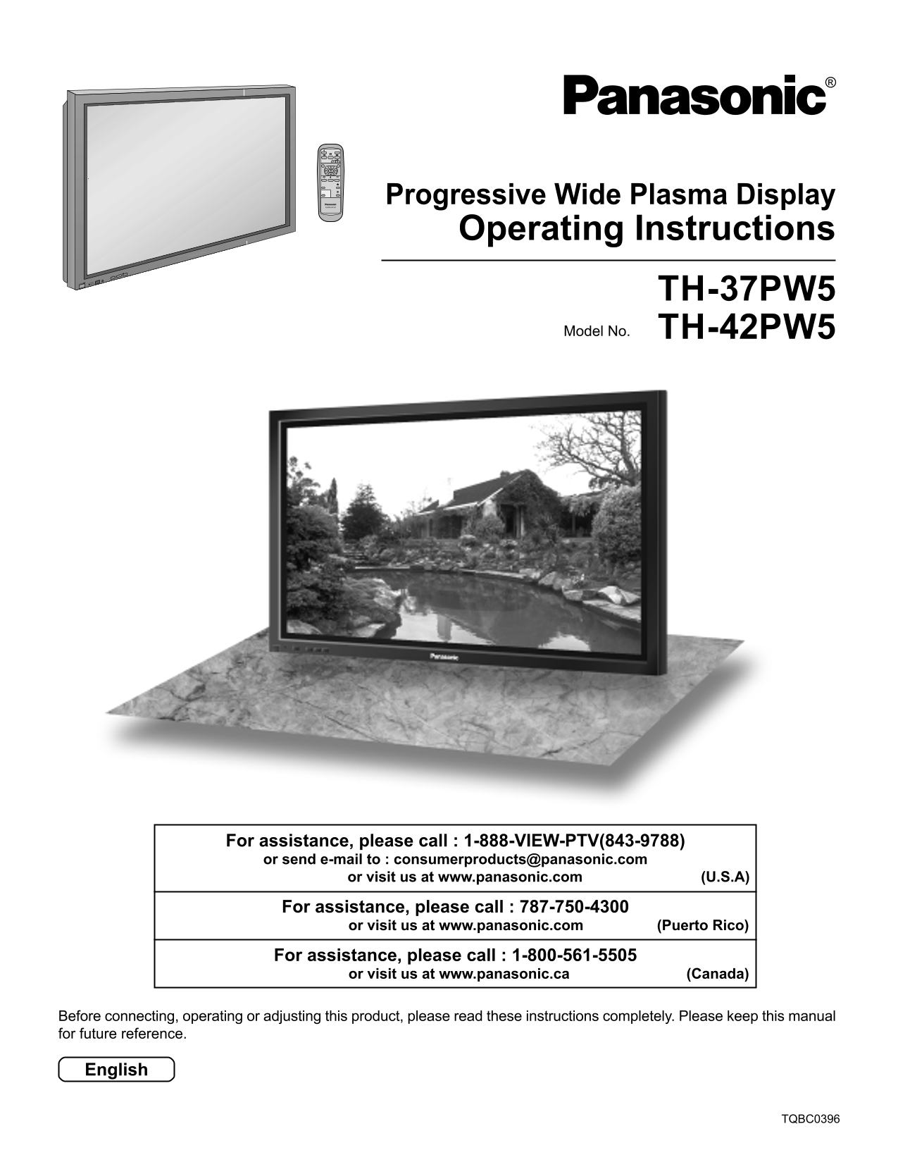
Progressive Wide Plasma Display PLASMA DISPLAY Operating Instructions INPUT — VOL + POWER / R - STANDBY G POWER ON TH-37PW5 TH-42PW5Model No. For assistance, please call : 1-888-VIEW-PTV(843-9788) or ...
Page 2
WARNING RISK OF ELECTRIC SHOCK DO NOT OPEN WARNING: To reduce the risk of electric shock, do not remove cover or back. No user-serviceable parts inside. Refer servicing to qualified service personnel....
Page 3
Important Safety Instructions 1) Read these instructions. All the safety and operating instructions should be read before the appliance is operated. 2) Keep these instructions. The safety and operatin...
Page 4
Dear Panasonic Customer Welcome to the Panasonic family of customers. We hope that you will have many years of enjoyment from your new Plasma Display. To obtain maximum benefit from your set, please r...
Page 5
FCC STATEMENT FCC STATEMENT This equipment has been tested and found to comply with the limits for a Class B digital device, pursuant to Part 15 of the FCC Rules. These limits are designed to provide ...
Page 6
Safety Precautions WARNING Set up Do not place the Plasma Display on sloped or unstable surfaces. • The Plasma Display may fall off or tip over. Do not place any objects on top of the Plasma Display. ...
Page 7
Safety Precautions CAUTION This Plasma Display is for use only with the following optional accessories. Use with any other type of optional accessories may cause instability which could result in the ...
Page 8
Accessories Accessories Supplied Check that you have the Accessories and items shown Operating Remote Control Batteries for the Remote AC cord Instruction book Transmitter Control Transmitter EUR64652...
Page 9
Remote Control Batteries Requires two AA batteries. 1. Turn the transmitter face down. 2. Install the batteries as shown in the 3. Replace the cover and slide in Press and slide off the battery batter...
Page 10
Basic Controls INPUT — VOL + R - STANDBY G POWER ON Main POWER TH-42PW5 ON/OFF Switch VOLUME Adjustment Remote control INPUT button Press the Volume Up “+” or sensor (VIDEO (S VIDEO), Down “–” button ...
Page 11
Connections SPEAKER SPEAKER Terminals (R) Terminals (L) AC cord connection (see page 18) – Cable fixing bands Secure any excess cables with bands, as required. Pass the attached cable fixing To secure...
Page 12
Connections Speakers connection When connecting the speakers, be sure to use only the optional accessory speakers. Refer to the speaker’s Installation Manual for details on speaker installation. Remov...
Page 13
Connections 3×RCA audio video cables connection (VCR) Audio Video OUT OUTR Video input to AUDIO-VIDEO RCA socket 3×RCA audio video cables Audio input to L/R sockets AUDIO S VIDEOVIDEO AV IN Notes: (1)...
Page 14
Connections RGB signal (R, G, B, HD, VD) connection RGB input to BNC-RCA R, G, B, HD, VD sockets adaptor plug Example of input signal source HDTV-compatible VCR 5×BNC RGB cables RGB camera AUDIO VD HD...
Page 15
Connections PC Input Terminals connection COMPUTER AUDIO PC IN POWER / R - STANDBY G POWER ON INPUT — VOL + Less than Conversion adapter Ferrite core (large size) (if necessary) 3" 15/16 (supplie...
Page 16
Connections Signal Names for D-sub 15P Connector Pin No. Signal Name Pin No. Signal Name Pin No. Signal Name GND (Ground) GND (Ground) GND (Ground) SDA GND (Ground) HD/SYNC GND (Ground) NC (not connec...
Page 17
Connections SERIAL Terminals connection The SERIAL terminal is used when the Plasma Display is controlled by a computer. COMPUTER Ferrite core (large size) SERIALRS-232C straight cable Pin layout for ...
Page 18
Power ON/OFF and Input Signal Selection AC cord connection Connecting the AC cord plug to the Plasma Display. Power ON/OFF Connecting the plug to the Wall Outlet Press the POWER switch on the Plasma D...
Page 19
Power ON/OFF and Input Signal Selection Select the Input Signal INPUT Press the INPUT button to select the input video signal desired from equipment such as a VCR which has been connected to the Plasm...
Page 20
On-Screen Menu Display from Remote Control To PICTURE adjust menu (see page 28) PICTURE NORMALIZE NORMAL PICTURE MENU STANDARD PICTURE BRIGHTNESS COLOR Press to select each TINT menu. 0SHARPNESS INPUT...
Page 21
On-Screen Menu Display from Remote Control To SIGNAL screen for VIDEO (see page 32, 33) SIGNAL [ VIDEO ] 3D Y/C FILTER (NTSC) ON COLOR SYSTEM AUTO Press to access “SIGNAL” setup menu. 3:2 PULLDOWN OFF...
Page 22
ASPECT Controls The Plasma Display will allow you to enjoy viewing the picture at its maximum size, including wide screen cinema format picture. ASPECT ASPECT button The aspect mode changes each time ...
Page 23
ASPECT Controls Picture Explanation NORMAL will display a 4:3 picture at its standard 4:3 NORMAL size. NORMAL ZOOM mode magnifies the central section of the picture. FULL will display the picture at i...
Page 24
Adjusting PICTURE POSITION/SIZE Adjusting screen PICTURE POS. /SIZE Press to display the PICTURE POS./ SIZE menu. INPUT SURROUND Press to select H-POS/H-SIZE/V-POS/ V-SIZE/CLOCK PHASE. PICTURE SOUND S...
Page 25
Adjusting PICTURE POS./SIZE When the Position Left “ ” button is pressed When the Position Right “ ” button is pressed H-POS When the Position Left “ ” button is pressed When the Position Right “ ” bu...
Page 26
SOUND Adjustment SOUND Press to display the Sound menu. INPUT Select to adjust each item. SURROUND Press to select the desired adjustment menu. Select the desired level by listening to the sound. PICT...
Page 27
SURROUND Controls SURROUND SURROUND Button The benefits of surround sound are enormous. You can be completely enveloped in sound; just as if you were at a concert hall or cinema. The surround setting ...
Page 28
PICTURE Adjustments PICTURE PICTURE Press to display the PICTURE menu. NORMALIZE NORMAL PICTURE MENU STANDARD PICTURE BRIGHTNESS COLOR TINT Select to adjust each item. 0SHARPNESS COLOR TEMP NORMAL Pre...
Page 29
PICTURE Adjustments Notes: Item Effect Adjustments (1) “COLOR” and “TINT” settings cannot Adjusts the proper picture contrast. PICTURE be adjusted for “RGB” and “PC” input Less More signal modes. (2) ...
Page 30
SCREENSAVER (For preventing after-images) Do not display a still picture, especially in 4:3 mode, for any length of time. If the display must remain on, a SCREENSAVER should be used. SET UP Press to d...
Page 31
SCREENSAVER SIDE BAR ADJUST Do not display a picture in 4:3 mode for an extended period, as side bars this can cause an after-image to remain on the side bars on either side of the display field. To p...
Page 32
SET UP for Input Signals COMPONENT/RGB IN SELECT Select to match the signals from the source connected to the COMPONENT/RGB input terminals. Y, PB, PR signals “COMPONENT” R, G, B, HD, VD signals “RGB”...
Page 33
SET UP for Input Signals COLOR SYSTEM / Panasonic AUTO Select SIGNAL from the “SET UP” menu during VIDEO (S VIDEO) input signal mode. (“SIGNAL [VIDEO]” menu is displayed.) SET UP COMPONENT/RGB-IN SELE...
Page 34
SET UP for Input Signals SYNC Select SIGNAL from the “SET UP” menu during RGB or PC input signal mode. SET UP COMPONENT/RGB-IN SELECT Press to adjust. SIGNAL SCREENSAVER OSD LANGUAGE ENGLISH (US) Pres...
Page 35
Troubleshooting Before you call for service, determine the symptoms and make a few simple checks as shown below. Symptoms Checks Picture Sound Electrical Appliances Cars/Motorcycles Fluorescent light ...
Page 38
Specifications TH-37PW5 TH-42PW5 Power Source 120 V AC, 50/60 Hz Power Consumption Maximum 325 W 395 W Stand-by condition 2.3 W 2.3 W Power off condition 0.8 W 0.8 W Plasma Display panel Drive method ...
Page 39
Specifications TH-37PW5 TH-42PW5 Accessories Supplied Remote Control Transmitter EUR646525 Batteries 2 × AA Size Ferrite core 1 × J0KF00000018, 2 × J0KG00000054 Fixing bands (TMME203 or TMME 187) × 2 ...
Page 40
Customer’s Record The model number and serial number of this product can be found on its rear panel. You should note this serial number in the space provided below and retain this book, plus your purc...