Page 1
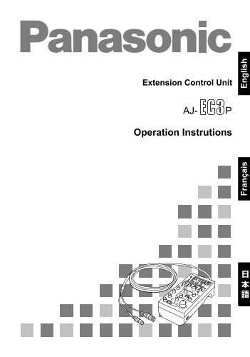
Extension Control Unit Operation Instrutions ra ça is lis
Page 2
Thank you for purchasing this AJ-EC3 Extension Control Unit (which will subsequently be referred to in these instructions as “the unit”). The unit features high performance and a variety of functions ...
Page 3
Features Features 1. The unit can be used to operate the VTR sections of DVCPRO, DVCPRO50 and DVCPRO HD camera recorders. ≥An ENABLE switch is provided to safeguard against operating errors. ≥VTR warn...
Page 4
Before use The unit’s functions may be restricted by the type of camera recorder used. Before use, therefore, check the camera recorder model and the functions which can be used with it. Model Functio...
Page 5
System connections The unit is connected to a camera recorder, monitor, etc. for use. The examples illustrated here show the system connections for mode 1 and modes 2/3. Mode 1 Camera recorder To VIDE...
Page 6
System connections Modes 2/3 Camera recorder BNC cable Cable (included) 6-pin cable To VIDEO OUT connector To CAM/BS (AJ-HDC20A: connector To ECU connector To HD HDI OUT connector) ECU AJ- BNC cable T...
Page 7
Parts and their functions Control panel Power switch Main power ON/OFF switch of the AJ-EC3P. START/STOP button ECU AJ- When this is pressed, the camera recorder starts ENABLE REW FF START/STOP record...
Page 8
Parts and their functions GAIN (gain selector) switch This is used to select the video amplifier’s gain depending on the lighting conditions that prevail during shooting. <Note> If the camera re...
Page 9
Parts and their functions PAINTING GAIN VRs R GAIN and B GAIN controls PAINTING ENABLE switch This is used to enable the PAINTING GAIN and BLACK VR controls. PAINTING BLACK VR R PEDESTAL and B PEDESTA...
Page 10
Parts and their functions Connector area CAM/BS connector This is used to connect the unit with the camera recorder or AJ-BS900P. VIDEO OUT connector The video signals with characters added are output...
Page 11
Menu displays for VIDEO OUT output Setting menu display for VIDEO OUT output When the SETUP switch is set to ON, the setting menus are displayed in the VIDEO OUT output. There are two kinds of setting...
Page 12
MAIN MENU 1 of 2 SYNCHRO SCAN screen VR DATA screen < SYNCHRO SCAN > < VR DATA > SYNCRO SCAN 1/50.6 MASTER PED +000 MASTER DTL +00 MASTER GAMMA 0.45 KNEE POINT 085% KNEE SLOPE +000 B GAIN ...
Page 13
MAIN MENU 1 of 2 KNEE/LEVEL screen FLARE/GAMMA screen < KNEE / LEVEL > < FLARE / GAMMA > MANUAL KNEE ON R FLARE WHITE CLIP ON G FLARE WHITE CLIP LVL 105% B FLARE AUTO KNEE POINT R GAMMA +0...
Page 14
MAIN MENU 2 of 2 CAMERA SETTING screen AUTO SHADING screen < CAMERA SETTING > < AUTO SHADING > DETAIL ON BLACK 2D LPF OFF WHITE SUPER COLOR ON BLACK COMPE. ON GAMMA ON WHITE COMPE. ON TEST...
Page 15
Shading adjustment When performing shading using the BLACK and WHITE items on the AUTO SHADING screen, proceed with the menu operations using the following black shading example as a reference. Shadin...
Page 16
Specifications Power requirements: DC 12 V Consumption: 125 m A indicates safety items. Allowable ambient temperature: 32 to 104 F (0 to 40 o C) Allowable relative humidity: 85% or less Dimensions: 3-...
Page 18
Nous vous remercions d’avoir choisi ce module de commande d’extension AJ-EC3P (qui sera simplement appelé “l’appareil” dans la suite de ce mode d’emploi). L’appareil offre de hautes performances et un...
Page 19
Caractéristiques Caractéristiques 1. L’appareil permet de piloter la section magnétoscope des camescopes DVCPRO, DVCPRO50 et DVCPRO HD. ≥Un commutateur ENABLE empêche les erreurs de manipulation. ≥Une...
Page 20
Avant l’utilisation Selon le camescope, il est possible que les fonctions de l’appareil soient limitées. En conséquence, avant l’utilisation, vérifier le modèle du camescope et les fonctions qui peuve...
Page 21
Raccordements du système L’appareil se raccorde à un camescope, un moniteur, etc. Les exemples montrent les raccordements du système pour le mode 1 et les modes 2/3. Mode 1 Camescope Vers le connecteu...
Page 22
Raccordements du système Modes 2/3 Camescope Câble BNC Câble (fourni) Câble à 6 broches Vers le connecteur Vers le connecteur ECU VIDEO OUT (AJ-HDC20A :Vers le ECU AJ- connecteur HC HDI OUT) Câble BNC...
Page 23
Les commandes et leurs fonctions Panneau de commande Interrupteur d’alimentation C’est l’interrupteur de mise sous/hors tension de l’AJ-EC3P. ECU AJ- Touche de marche/arrêt (START/STOP) ENABLE REW FF ...
Page 24
Les commandes et leurs fonctions Sélecteur de gain (GAIN) Il permet de sélectionner le gain de l’amplificateur vidéo en fonction des conditions d’éclairage qui prévalent pendant la prise de vues. <...
Page 25
Les commandes et leurs fonctions Commutateur d’obturateur (SHUTTER) Le régler sur ON pour pouvoir utiliser l’obturateur électronique. Sélecteur de vitesse d’obturation (SHUTTER SPEED) Il permet de sél...
Page 26
Les commandes et leurs fonctions Commutateur CHECK Quand on appuie sur cette touche, la valeur du gain, la position du filtre et la valeur du diaphragme s’affichent dans cet ordre sur la LED d’afficha...
Page 27
Affichage des menus de la sortie vidéo Réglage des menus de la sortie vidéo (VIDEO OUT) Lorsque le commutateur SETUP est réglé sur ON, les menus de réglage s’affichent à la sortie VIDEO OUT. Il y a de...
Page 28
Ecrans de MAIN MENU 1 de 2 Ecran SYNCHRO SCAN Ecran VR DATA < SYNCHRO SCAN > < VR DATA > SYNCRO SCAN 1/50.6 MASTER PED +000 MASTER DTL +00 MASTER GAMMA 0.45 KNEE POINT 085% KNEE SLOPE +000...
Page 29
Ecrans de MAIN MENU 1 de 2 Ecran KNEE/LEVEL Ecran FLARE/GAMMA < KNEE / LEVEL > < FLARE / GAMMA > MANUAL KNEE ON R FLARE WHITE CLIP ON G FLARE WHITE CLIP LVL 105% B FLARE AUTO KNEE POINT R ...
Page 30
Ecrans de MAIN MENU 2 de 2 Ecran CAMERA SETTING Ecran AUTO SHADING < CAMERA SETTING > < AUTO SHADING > DETAIL ON BLACK 2D LPF OFF WHITE SUPER COLOR ON BLACK COMPE. ON GAMMA ON WHITE COMPE....
Page 31
Réglage de l’ombrage Pour effectuer l’ombrage avec les rubriques BLACK et WHITE de l’écran AUTO SHADING, procéder comme indiqué ci-dessous dans l’exemple d’ombrage du noir, donné à titre de référence....
Page 32
Fiche technique Alimentation : 12 V CC Consommation : 125 m A Informations concernant la sécurité Température ambiante admissible : 0 à 40°C Humidité relative admissible : 85% maximum Dimensions : 82(...
Page 33
ra ça is
Page 34
PANASONIC BROADCAST & DIGITAL SYSTEMS COMPANY DIVISION OF MATSUSHITA ELECTRIC CORPORATION OF AMERICA Executive Office: 3330 Cahuenga Blvd W., Los Angeles, CA 90068 (323) 436-3500 EASTERN ZONE: One...