Page 1
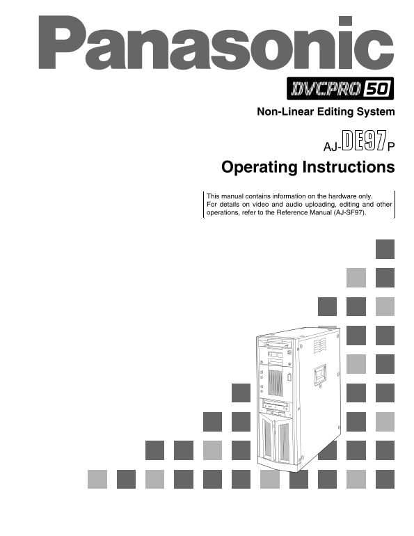
Non-Linear Editing System Operating Instructions This manual contains information on the hardware only. For details on video and audio uploading, editing and other operations, refer to the Reference M...
Page 2
IMPORTANT “Unauthorized recording of copyrighted television programs, video tapes and other materials may infringe the right of copyright owners and be contrary to copyright laws.” FCC Note: CAUTION T...
Page 3
Contents Features . . . . . . . . . . . . . . . . . . . . . . . . . . . . . . . . . . . . . . . . . . . . . . 4 Warning. . . . . . . . . . . . . . . . . . . . . . . . . . . . . . . . . . . . . . . . ....
Page 4
Features All-in-one tower design This system contains a internal VTR for uploading and downloading data. This feature translates into savings in terms of both the cost and space required for an extern...
Page 5
System Configuration Do not subject the supplied mouse, keyboard or cables to strong bumps or shocks. Doing so could damage them. Keyboard Main unit Mouse Power cord When the SCSI hard disk drive for ...
Page 6
Parts and Their Functions Front Panel 6Phones volume control This is used to adjust the headphones volume and the monitor output volume. 7Mic jack The microphone is connected here for voice-over editi...
Page 7
Parts and Their Functions LED Display Panel LED display panel (Yellow) (Amber)(Green) CH CONDITION VTRAUTO OFF 1AUTO OFF lamp 4VTR lamp This lights when trouble has occurred in the unit’s This lights ...
Page 8
Parts and Their Functions Rear Panel 5Analog composite video signal input connectors [ANALOG, VIDEO INPUT, VIDEO IN] SIGNAL GND SDI/SDIT AC IN The analog composite video signals are supplied to (OPTIO...
Page 9
Parts and Their Functions Rear Panel SIGNAL GND SDI/SDIT (OPTION) AC IN IN OUT SDI/SDIT SDI/SDIT ACTIVE THROUGH SDI FUSE F1 125V FUSE F2 125V ANALOG VIDEO INPUT VIDEO OUTPUT VIDEO IN REF VODEO IN PB P...
Page 10
Parts and Their Functions Rear Panel SIGNAL GND SDI/SDIT (OPTION) AC IN IN OUT SDI/SDIT SDI/SDIT ACTIVE THROUGH SDI FUSE F1 125V FUSE F2 125V ANALOG VIDEO INPUT VIDEO OUTPUT VIDEO IN REF VODEO IN PB P...
Page 11
Parts and Their Functions Rear Panel SIGNAL GND SDI/SDIT (OPTION) AC IN IN OUT SDI/SDIT SDI/SDIT ACTIVE THROUGH SDI FUSE F1 125V FUSE F2 125V ANALOG VIDEO INPUT VIDEO OUTPUT VIDEO IN REF VODEO IN PB P...
Page 12
Connections Basic Connections (Connecting the power cord, keyboard, mouse and system cables) 1. Connect the keyboard and mouse to their respective connectors. 2. Connect the power cord. Main unit SIGN...
Page 13
Connections Monitor Connections Connecting the personal computer monitor (S-VGA) Connect the computer monitor to the SVGA I/F connector. Use a monitor which meets the following conditions. Default set...
Page 14
Connections VTR Connections Connect a commercial video cassette recorder/player COMPONENT VIDEO OUT Main unit Coaxial cable (with BNC connectors) (Y/PB/PR) SIGNAL GND SDI/SDIT (OPTION) AC IN IN OUT SD...
Page 15
Connections Audio Equipment Connections Connect speakers with built-in amplifiers, a cassette deck or other audio unit. Main unit SIGNAL GND SDI/SDIT (OPTION) AC IN IN OUT SDI/SDIT SDI/SDIT ACTIVE THR...
Page 16
Connections Editing Control Pad Connections Connect the editing control pad (AJ-A77) available as an option. Main unit SIGNAL GND SDI/SDIT (OPTION) AC IN IN OUT SDI/SDIT SDI/SDIT ACTIVE THROUGH SDI FU...
Page 17
System Startup and Exit System Startup Set the power switches of the peripheral units Main unit power switch to ON. Set the power switch on the main unit to ON. The HDD access display lamp on the main...
Page 18
System Startup and Exit System Exit Click in the tool box. A confirmation panel appears. Computer monitor Tool box Bin window Bin manager Click if you wish to exit the system. Confirmation panel The W...
Page 19
System Startup and Exit Computer monitor/Windows NT exit screen Click Windows NT shutdown. Confirmation panel A confirmation panel now appears. Select the exit method and click if you wish to exit Win...
Page 20
Troubleshooting If you believe that something is wrong with your product, take the time to check whether the product has been operated incorrectly before asking a service engineer to conduct repairs. ...
Page 21
Troubleshooting Troubleshooting Chart Use the Troubleshooting Chart to remedy certain symptoms. Find the “Symptom” concerned in the left-hand column of the table, and take the “Suggested remedial acti...
Page 22
Troubleshooting Symptoms related to floppy disk drive Symptom Suggested remedial action The floppy disk drive’s access lamp OHas the product been started up with a floppy disk already inserted in rema...
Page 23
Troubleshooting Symptoms related to the keyboard or mouse Symptom Suggested remedial action All or some of the keys on the OAre you using the keyboard provided with the product? keyboard fail to funct...
Page 24
Troubleshooting Symptoms related to memory Symptom Suggested remedial action What is displayed as the memory OHas the memory been increased inappropriately or has the memory size differs from the size...
Page 25
Troubleshooting Symptoms related to software, operating system or operations Symptom Suggested remedial action A warning dialogue appears when OWere the mouse and other peripheral devices connected af...
Page 26
Troubleshooting Other symptoms Symptom Suggested remedial action The playback images of the tape OHas the power of the monitor (Video) for monitoring the pictures inserted into the internal VTR are be...
Page 27
Troubleshooting Other symptoms Symptom Suggested remedial action The personal computer’s monitor Is the supply voltage within the rated range? screen display suddenly goes Use of an uninterruptible re...
Page 28
Connector Signals VIDEO INPUT Y, PB, PR (ANALOG) BNCa3 VIDEO IN BNCa2 Loop-through, 75 Ω termination switch provided REF VIDEO IN BNCa2 Loop-through, 75 Ω termination switch provided VIDEO OUTPUT Y, P...
Page 29
Connector Signals RGB I/F SCSI CH1/A, CH2/B Pin No. Signal Pin No. Signal Pin No. Signal CRV + DB (12) – DB (12) CGV + DB (13) – DB (13) CBV + DB (14) – DB (14) un used + DB (15) – DB (15) 5~8 GND + D...
Page 30
Error Items When the WARNING lamp is lighted Monitor display Description VTR operation This is displayed when the fan motor stops.FAN STOP Operation continues NO RF This appears during playback when a...
Page 31
Error Items When the AUTO OFF lamp is lighted Description Monitor display VTR operation DRUM ROTA TOO SLOW If the cylinder motor speed is abnormally low, the AUTO STOP OFF lamp lights, and the message...
Page 32
Error Items When the AUTO OFF lamp is lighted Description Monitor display VTR operation S-FF/REW TIMEOVER If the start/end processing operation is not completed, the STOP AUTO OFF lamp lights, and the...
Page 33
Maintenance and Care In order to deliver a high performance, this unit contains some precision-made mechanisms. To keep the unit in perfect working order for as long as possible, remember to maintain ...
Page 34
Specifications [GENERAL] [VIDEO] Sampling frequency: Power supply: 120V AC(±10%), 50Hz – 60 Hz Y: 13.5 MHz Rated current: 4.0 A PB/PR: 6.75 MHz (4:2:2) PB/PR: 3.375 MHz (4:1:1) Ambient operating tempe...
Page 35
Specifications [INPUT/OUTPUT CONNECTORS] Video input connectors Analog composite: BNCa2 (loop-through configuration) Analog component (Y, PB, PR): BNCa3 Analog reference video: BNCa2 (loop-through con...
Page 36
PANASONIC BROADCAST & TELEVISION SYSTEMS COMPANY DIVISION OF MATSUSHITA ELECTRIC CORPORATION OF AMERICA Executive Office: 3330 Cahuenga Blvd W., Los Angeles, CA 90068 (323) 436-3500 EASTERN ZONE: ...